When fully warmed up it is shockingly transparent. I'm listening to RR "The Soldier's Tale" I have a much greater sense of where the instruments are physically in the mix than I recall.
I think I do need to get quieter "quiet" fans for the media server, they are actually significantly above the room noise floor even on the lowest speed setting.
I think I do need to get quieter "quiet" fans for the media server, they are actually significantly above the room noise floor even on the lowest speed setting.
I've ordered a couple of SPDIF transformers, specifically the Newava S22160 and the S22133 which has an electrostatic shield between the primary and secondary. I will use one or the other to isolate the spdif from the internal dac circuitry.
The increase in secondary load represents a significant improvement, but tracking down and reducing the noise coupled into the dac was the bigger win.
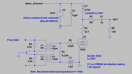
I've attached the latest schematic, the only change is in the value of R2.
Edit (2013-01-11): This is the most current schematic
The increase in secondary load represents a significant improvement, but tracking down and reducing the noise coupled into the dac was the bigger win.
I've attached the latest schematic, the only change is in the value of R2.
Edit (2013-01-11): This is the most current schematic
Attachments
Something to note here is that R1 in conjunction with the transformer's leakage inductance determines the HF corner. Values of 10 - 12.1K are not unreasonable and result in a very slight increase (few tenths of a dB) in output level and increase the bandwidth significantly.
IIRC with the 8.25K load resistors the -1dB point is around 20kHz. (Adequate for my purposes since my vintage JBL 075 horn tweeters crash precipitously at 16kHz)
IIRC with the 8.25K load resistors the -1dB point is around 20kHz. (Adequate for my purposes since my vintage JBL 075 horn tweeters crash precipitously at 16kHz)
See a slightly different implementation by clivem here: http://www.diyaudio.com/forums/digi...-pcm1794-waveio-usb-input-13.html#post3321357
I've ordered a couple of SPDIF transformers, specifically the Newava S22160 and the S22133 which has an electrostatic shield between the primary and secondary. I will use one or the other to isolate the spdif from the internal dac circuitry.
The increase in secondary load represents a significant improvement, but tracking down and reducing the noise coupled into the dac was the bigger win.
I've attached the latest schematic, the only change is in the value of R2.
Edit (2013-01-11): This is the most current schematic
Hi, Kevin,
I'm curious to read your subjective reasons for implementing a choke load for the triode over an CCS or gyrator. I've before read comments by Bas Horneman, Thorsten Loesch, and others generally extolling the sound character of choke loaded triodes. However, I don't believe I've ever actually heard such an implementation with my own ears.
I'm exploring building an I/V circuit that is topologically like the one you have shown in this thread, except with a MOSFET based gyrator plate load. Since audio chokes are rather costly, and objectively don't perform as well as a solid-state CCS or gyrator I would very much like to have the benefit of your subjective experience before selecting a direction and purchasing parts.
Last edited:
Hi Ken,
A thoughtful question.. 😀 I've experimented with tube based gyrators, choke and transformers. I admit I have what is possibly a fairly irrational dislike of semi-conductors in a tube signal path despite the very obvious and objective advantages.. I've come to prefer transformer or chokes in a number of applications where I need to drive low impedances or lines, compared to tube based gyrators the choke approach seems to offer a greater sense of dynamics and linearity can be quite good. (Headroom is not an issue even at fairly low plate voltages, and choke loading is quite practical with the high transconductance / low rp tube types I prefer) Lundahl makes good chokes that are not too exorbitant IMO, no better way to answer the question than to try it yourself.
A thoughtful question.. 😀 I've experimented with tube based gyrators, choke and transformers. I admit I have what is possibly a fairly irrational dislike of semi-conductors in a tube signal path despite the very obvious and objective advantages.. I've come to prefer transformer or chokes in a number of applications where I need to drive low impedances or lines, compared to tube based gyrators the choke approach seems to offer a greater sense of dynamics and linearity can be quite good. (Headroom is not an issue even at fairly low plate voltages, and choke loading is quite practical with the high transconductance / low rp tube types I prefer) Lundahl makes good chokes that are not too exorbitant IMO, no better way to answer the question than to try it yourself.
It's been about 4 months since I last posted on the I/V converter. It has received regular use over the intervening months with no issues noted, and I have to say it is certainly my best sounding I/V converter design yet. I am frequently surprised at how much better previously mediocre sounding rips of cds actually sound.
I still debate the wisdom of so savagely limiting the HF bandwidth but it can be increased easily just by increasing the value of the load resistor on the secondary of the I/V transformer. In any event my horn tweeters roll off at 17kHz (ancient JBL alnico 075s) so for me a bw of -1dB @ 20kHz or better is sufficient.
I ended up not using a spdif transformer at the input of the dac as the source already has a transformer, and I was not able to achieve reliable lock with the transformer installed. (The source is a Stello U3 asynchronous USB to spdif converter based on the XMOS chipset, probably an even better solution would be direct to I2C but this works fine..)
While not currently in a position to address the issues I have identified over the past few months I will mention them and what I intend to do to address them.
I am going to double the value of the I/V conversion resistors (or select the next higher available value above that.)
I listen to a lot of digital material that is not recorded higher than -20dBFS and the current gain is insufficient in the context of the system requirements. Possibly something up to 6Vrms out is a good compromise for FS and well within the capability of my other electronics.
- I am going to increase the HF bandwidth to something closer to the transformer's design limits. I think I was too extreme in my choice of roll-off point. Let other parts of the system do it, eh..
- Gain is insufficient for most material on my server except for pop which as I get older I listen to less and less.
I am going to double the value of the I/V conversion resistors (or select the next higher available value above that.)
I listen to a lot of digital material that is not recorded higher than -20dBFS and the current gain is insufficient in the context of the system requirements. Possibly something up to 6Vrms out is a good compromise for FS and well within the capability of my other electronics.
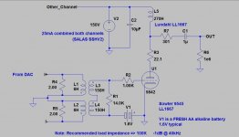
As I threatened I have made a change which increases the HF bandwidth by approximately an octave to 40kHz.
Next I plan to boost output by approximately 6dB which will account both for the higher signal levels I designed the system for and to compensate for some program material where the average level is rather lower than normal.
Next I plan to boost output by approximately 6dB which will account both for the higher signal levels I designed the system for and to compensate for some program material where the average level is rather lower than normal.
Attachments
Well I've had about 3.5 hours of listening time with the increased HF bandwidth, initially I felt it sounded a bit harsher, but having allowed it to warm up thoroughly it seems to have mellowed or I got use to it.. 😛
Interestingly there does seem to be a bit more depth on some recently played and familiar recordings, not sure why this would be since the system really cannot reproduce any of the added octave of treble response, perhaps I just over-damped the secondary of the I/V transformer. I've not looked at the square wave response of the DAC which I would not expect to be particularly good - now I am curious and will have to have a look on the bench at some point. I can drive the DAC via spdif coax and use audiotester to generate test wave forms at several different sample rates.
Interestingly there does seem to be a bit more depth on some recently played and familiar recordings, not sure why this would be since the system really cannot reproduce any of the added octave of treble response, perhaps I just over-damped the secondary of the I/V transformer. I've not looked at the square wave response of the DAC which I would not expect to be particularly good - now I am curious and will have to have a look on the bench at some point. I can drive the DAC via spdif coax and use audiotester to generate test wave forms at several different sample rates.
Gain Increase
As I previously mentioned I like to run my sources very hot into a line stage with very limited gain, designed for high signal levels - this gives me better overall SNR since most of the gain is concentrated in the sources. The line stage has a maximum gain of only 4dB..
I've changed R4 and R5 from 2 ohms to 3 ohms in order to boost 0dBfs to ~6.0Vrms. This provides margin for recordings that have rather low average levels while at the other end levels are not sufficiently high to clip the analog output stage.
R4, R5:
1 ohm for ~2.0Vrms
2 ohms for ~4.0Vrms
3 ohms for ~6.0Vrms
4 ohms for ~8.0Vrms
Values given are valid only for PCM1794A in mono mode with current summing in the DAC output. (BPZ -12.4mA, 15.6mApp @ FS)
I'm using Holco H4 1 ohm resistors in series for the resistive component of the I/V conversion. Finding low value resistors in the right values is difficult. Finding ones that don't degrade the performance of the DAC is even harder.
I've also evaluated single 4.02 ohm 1% 1/8W thin film leaded resistors which did not sound great. (Obvious loss of low level detail.)
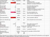
Results in spreadsheet are for the analog portion of the dac. Note that a substantial noise penalty is inflicted by the grid stopper (R2) resistance, it may be the case that 100 - 220 ohms would be sufficient with care in layout. Numerous errors in the original calculations have been corrected. (Think I have it right finally)
As I previously mentioned I like to run my sources very hot into a line stage with very limited gain, designed for high signal levels - this gives me better overall SNR since most of the gain is concentrated in the sources. The line stage has a maximum gain of only 4dB..
I've changed R4 and R5 from 2 ohms to 3 ohms in order to boost 0dBfs to ~6.0Vrms. This provides margin for recordings that have rather low average levels while at the other end levels are not sufficiently high to clip the analog output stage.
R4, R5:
1 ohm for ~2.0Vrms
2 ohms for ~4.0Vrms
3 ohms for ~6.0Vrms
4 ohms for ~8.0Vrms
Values given are valid only for PCM1794A in mono mode with current summing in the DAC output. (BPZ -12.4mA, 15.6mApp @ FS)
I'm using Holco H4 1 ohm resistors in series for the resistive component of the I/V conversion. Finding low value resistors in the right values is difficult. Finding ones that don't degrade the performance of the DAC is even harder.
I've also evaluated single 4.02 ohm 1% 1/8W thin film leaded resistors which did not sound great. (Obvious loss of low level detail.)
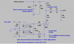
Results in spreadsheet are for the analog portion of the dac. Note that a substantial noise penalty is inflicted by the grid stopper (R2) resistance, it may be the case that 100 - 220 ohms would be sufficient with care in layout. Numerous errors in the original calculations have been corrected. (Think I have it right finally)
Attachments
Thanks for continuing to post the evoluton of your DAC setup, Kevin. I really appreciate hearing about the path you're taking with it.
Regards,
John
Regards,
John
John, I'm delighted that anyone at all is following this thread at this point.
I hope a few people will build this design for use with the PCM1794A or indeed any current output dac chip they desire. It is not inexpensive to build which I suspect is why there is not a lot of interest in this design. The performance is quite good, noise is imperceptible. I need to remeasure the dac to see how close the married digital and analog electronics get to the calculations.
The boost in gain (3.5dB) was just what was needed in conjunction with the increased bandwidth. Output levels are much closer to the analog portion of my system but not excessive.
This is my best sounding dac so far..
My implementation is similar. I'm using the PCM1794A in stereo mode w/ 18R I/V resistors. For a step-up, I'm using the MQ B7 500:15k.
I have the opposite sitation than you in regards to gain -- <400mVRMS is more than sufficient to clip the output stage. So, I have no gain stage in the DAC. Just USB -> DAC -> I/V -> Step-up -> 100k pot for volume control.
Your posts allude to the detail that I haven't yet grappled with, and that is whether or not my current arrangement minimizes system-wide noise. Very well could be that it would be better from a SNR perspective to move some gain from the amplifier to the DAC.
Regards,
John
Generally placing as much gain as early as possible in the signal chain is a win from a noise perspective. Each successive stage makes its own noise contribution as well as further amplifying the noise of preceding stages.
The line stage has 4dB of gain and my 20W SE power amplifier has ~20dB of voltage gain overall.
The line stage has 4dB of gain and my 20W SE power amplifier has ~20dB of voltage gain overall.
- Status
- Not open for further replies.
- Home
- Amplifiers
- Tubes / Valves
- Tube And Transformer I/V Converter For Differential Current DAC