Thank you Franwoodturner-fran said:Damp it with some lightweight material - I used a kind of neoprene foam that was sticky on one side.
Some reading on the armageddon:
http://www.pinkfishmedia.net/forum/archive/index.php/t-22291.html
and:
http://www.areyoulocal.com/Geddon.asp
and:
http://www.neilmcbride.co.uk/ttpsu.html
Basically get a big transformer with 2 x 55V secondaries. Wire these in series to give you a nominal 110V. This is then adjusted down by adding in a series resistor (between 3-10K 5W) to bring down the voltage to around 65-70V. A 0.22uF cap is used to create a phase shift for the second winding on the motor. IIRC, you tap off the the 2 coloured wires before and after this cap. What you want is the lowest volts that allows the TT to start reliably - this also means the lowest amount of vibration in teh motor. I believe that Naim use a 300Va transformer, but i think I had a 160Va one.
Finally I am starting to grasp the concept.
My first question is:
The RD80 has the motor connected directly to the mains (220v 50Hz). From what I read, I must power it wih only 65-70v ??

I need to read a lot before I start this project. I must fully understand how this motor works. Could you please point me in the right direction ?
Regards
Ricardo
Yes...
The motor is set to run on 110V supply and either 50 or 60 Hz. What happens is that in the control circuit, a capacitor causes a phase shift in the AC sine wave. This means that before and after this cap, the sine wave will be opposite. One of the windings of the motor is connected before the cap, and the other after the cap. The other 2 motor wires are connected to the other leg of the mains supply (eg neutral).
Heres the heart of the improvement however. At 110V the motor will vibrate quite a bit. So the idea is to use a power resistor to drop the voltage which will reduce the vibration, hence improved sonics. Drop it too much and the motor won't start the platter on its own, drop it too little and you don't get all the benefits.
Just use a 5W resistor to do this drop. If you buy say a 3K, 6K8, 8K and 9K resistors, you can try each one and see what voltage you get in the circuit. If you go much below the 70V mentioned above, the platter may not reliably start.
So the circuit works like this:
Designate one wire from the transformer as "positive" and one as "negative" (even thought this is AC, not DC). Join the 2 grey wires to the "negative" wire. Add the dropping resistor to the "positive" one. then add the capacitor (0.22uf). One of the remaining motor wires goes before the cap, and the other after the cap.
Size the resistor to give you ~70V - measure the voltages while the motor is actually running the platter.
Thats it really!
Fran
Disclaimer: these are mains voltages that can kill you. If you don't know how to deal with such voltages carefully, get someone who does to sort it out for you.
Thank you Franwoodturner-fran said:
Disclaimer: these are mains voltages that can kill you. If you don't know how to deal with such voltages carefully, get someone who does to sort it out for you.
Now I understand perfectly what to aim for.... less voltage = less vibration.
So the transformer is needed to get 110v from mains 220v and then do a voltage drop using only a resistor !
Note:
Rest assured I know mains can Kill me. but worst ... can surelly kill the TT and all the other valued modded components 😀
Regards
Ricardo
woodturner-fran said:Yes...
The motor is set to run on 110V supply and either 50 or 60 Hz. What happens is that in the control circuit, a capacitor causes a phase shift in the AC sine wave. This means that before and after this cap, the sine wave will be opposite. One of the windings of the motor is connected before the cap, and the other after the cap. The other 2 motor wires are connected to the other leg of the mains supply (eg neutral).
Hi Fran
I still cannot figure out my TT motor setup:
The motor is connected directly to the mains 220.
If the motor is set to run at 110v, how does the voltage drop happen ?
I hope this question does not sound stupid.... I must understand the basics first.
Best regards
Ricardo
No, you will find its not connected directly to the mains.... if you have a look underneath you will see that the power cord goes to a circuit board embedded in the left hand side of the plinth. In there is a big power resistor that drops the voltage down. You will also see the cap for adjusting the phase for the second winding.
What you are doing is using a big transformer to drop this most of the way and then using a smaller resistor to fine tune the voltage.
Fran
What you are doing is using a big transformer to drop this most of the way and then using a smaller resistor to fine tune the voltage.
Fran
a fairly interesting thing to try...
might be to modify the DIY'geddon so that you start with 110V (bypass the capacitor and resistor ), and once up to speed, switch the capacitor and resistors into the circuit. That way you would get higher voltage and torque to start, but once up to speed, reduced motor noise.
stew
might be to modify the DIY'geddon so that you start with 110V (bypass the capacitor and resistor ), and once up to speed, switch the capacitor and resistors into the circuit. That way you would get higher voltage and torque to start, but once up to speed, reduced motor noise.
stew
Thank you Franwoodturner-fran said:No, you will find its not connected directly to the mains.... if you have a look underneath you will see that the power cord goes to a circuit board embedded in the left hand side of the plinth. In there is a big power resistor that drops the voltage down. You will also see the cap for adjusting the phase for the second winding.
What you are doing is using a big transformer to drop this most of the way and then using a smaller resistor to fine tune the voltage.
Now everything begins to make sence....
So the big power resistor drops voltage from 220v to 110v actually.
Regards
Ricardo
Re: a fairly interesting thing to try...
This is a very good idea... can you post any schematics ?
Regards
Ricardo
Hi StewNanook said:might be to modify the DIY'geddon so that you start with 110V (bypass the capacitor and resistor ), and once up to speed, switch the capacitor and resistors into the circuit. That way you would get higher voltage and torque to start, but once up to speed, reduced motor noise.
This is a very good idea... can you post any schematics ?
Regards
Ricardo
RCruz....
just use a momentary switch , or a toggle (2 position ) and wire the switch to bypass the resistors and connect directly to the connection to the motor on one leg of the switch, while the other is disconnected (double pole, double throw). In one position, 110V, the other, the reduced voltage (whatever you decide upon)
stew
Re: RCruz....
Another question.... As I do not have a suitable TX (I must buy one), could I just increase the power resistor in order to get a lower voltage in the motor ?
Ricardo
Thank you StewNanook said:just use a momentary switch , or a toggle (2 position ) and wire the switch to bypass the resistors and connect directly to the connection to the motor on one leg of the switch, while the other is disconnected (double pole, double throw). In one position, 110V, the other, the reduced voltage (whatever you decide upon)
Another question.... As I do not have a suitable TX (I must buy one), could I just increase the power resistor in order to get a lower voltage in the motor ?
Ricardo
RCruz....transfromerless and larger power resistor?
I am assuming you are in a 220V country...
If suitably large (wirewound?) resistors are available for 300V (just to be safe), then perhaps only resistors could be used. The current draw is not huge. The AC voltage then must be measured very carefully (accurately), and step down resistors and caps as in the 'geddon could be used. A good quality variable resistor could be used as well, to get it right where you need to be. Transformers need not be expensive.
You could always use my default power supply: an MP3 player or old cd player hooked up to a large power amplifier, feeding a 50Hz or 60Hz signal as required. Adjust the mp3 player to be in the linear range of its operation (don't pin the volume setting), and play it through a discarded or un-used , good quality integraded amplifier ). You could even record a second channel, 90 degrees out of phase to the first and use that as the second input to the motor.
But be warned, I've been criticized for suggesting this to others, as being wastefull, etc. If you do so, do so knowing you may be "chastised" for using this Brute Force method.
stew
mmmm, I think the whole idea of the arageddon is in the transformer. Really without it you might as well just stick with the stock power supply. After all it does work!
Fran
Fran
Re: RCruz....transfromerless and larger power resistor?
I do have a pair of Denon POA 6600A monoblocks.
One of them is damaged but the other works perfectly.
maybe I can experiement but my wife will not agree with me.
Just joking.......
I will think about all the possibilities and report the results.
Thank you again.
Regards
Ricardo
Well StewNanook said:I am assuming you are in a 220V country...
If suitably large (wirewound?) resistors are available for 300V (just to be safe), then perhaps only resistors could be used. The current draw is not huge. The AC voltage then must be measured very carefully (accurately), and step down resistors and caps as in the 'geddon could be used. A good quality variable resistor could be used as well, to get it right where you need to be. Transformers need not be expensive.
You could always use my default power supply: an MP3 player or old cd player hooked up to a large power amplifier, feeding a 50Hz or 60Hz signal as required. Adjust the mp3 player to be in the linear range of its operation (don't pin the volume setting), and play it through a discarded or un-used , good quality integraded amplifier ). You could even record a second channel, 90 degrees out of phase to the first and use that as the second input to the motor.
But be warned, I've been criticized for suggesting this to others, as being wastefull, etc. If you do so, do so knowing you may be "chastised" for using this Brute Force method.
I do have a pair of Denon POA 6600A monoblocks.
One of them is damaged but the other works perfectly.
maybe I can experiement but my wife will not agree with me.
Just joking.......
I will think about all the possibilities and report the results.
Thank you again.
Regards
Ricardo
Hi Franwoodturner-fran said:mmmm, I think the whole idea of the arageddon is in the transformer. Really without it you might as well just stick with the stock power supply. After all it does work!
Just found a suitable TX in RS.
They sell a 220v primary - 2x55v secondary for 45€...
There is a 300VA and a 500VA option. What should I choose ?
Now about the resistor and cap:
What should be the best resistor wattage ?
Can I place the cap + resistor inside the outboard PSU ? Or must the cap be near the motor ?
I understand the cap makes a 90º schift in the AC phase.
What is the purpose of this schift ?
I believe the RD80 uses a synchronous 24 pole with two windings, so one is in phase with the mains and the other advanced 90º right ?
Is this intended to reduce cogging ?
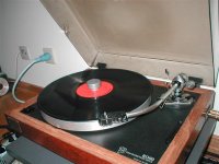
PS:
Pic of the beast
Regards
Ricardo
Attachments
Whatever one of those transformers is best value. I don't think there will be a big difference between them, so just pick the biggest one that is best value for money.
Get at least 5W resistors, say 2 x 1K, 1x 3K, 1x 6.8K and one around 9K. With those in parallel or series you should be able to hit the right voltage.
Yes the cap and resistors can all be in a box well away from the TT.
Yes, you are right. What happens is that the phases work on each winding alternately so that the motor turns at the correct speed depending on the mains frequency.
Looks like you are on your way....
Fran
Hi Franwoodturner-fran said:
Looks like you are on your way....
You made it possible with your the precious help.
I will be reporting the evolutions while building this psu.

....10 minutes latter....
Do you have any knowledge about the small disc used inside the bearing (between the spindle and the captive ball) ?
I recently bought one fromStuart (UK) but it seems too small for the large spindle on the RD80. How can I fix it inside the bearing ?
Ricardo
mmm, no, I don't know that one. On my bearing there is no captive ball - just the end of the spindle is rounded. If it is a thrust plate, then the usual place would be on the bottom of the bearing well.
Often a good plan is to rinse out the bearing well with some white spirit/solvent, blow it out with an air line, then put a drop of oil on the bottom of the well, fit the thrust plate, fill to just below the bottom register of the well and then fit the spindle in place. Allow it to settle, maybe help that by putting the platter on top. Some excess oil should spill out the top of the bearing. Try to not rotate the bearing until the oil has come out the top.
Mine has a linn basik arm - what arm is that on yours? What cartridge/phonostage are you going to use?
Fran
woodturner-fran said:
Mine has a linn basik arm - what arm is that on yours? What cartridge/phonostage are you going to use?
Myne has a SME3009 lightweight (fixed headshell) with a Benz ACE medium output (0.8mv) feeding a Meridian 101 preamp with stock MM phonostage.
The pic I posted before still has the Denon 160.
Soundstage is incomparably better than my super modded CD53 but lacks a bit of low end definition.
Medium registers are very sweet and true (SME style).
..edit..
What do you think of these springs ?
http://cgi.ebay.com/ws/eBayISAPI.dl...rkparms=algo=CRX&its=S%2BI&itu=UCI%2BSI&otn=4
Ricardo
yeah, they are what I ftted to mine - although the ones that I took out of it were not the black ones. I remember reading somewhere that they 2 types were meant to be different ....
I'd say fire ahead and go for it.
Fran
I'd say fire ahead and go for it.
Fran
I also have a TT with domed pulley. As I like very much the way it sounds with a belt made of dental floss I placed 2 o rings of the right diameter in the pulley, so they keep the belt in the right position. It works on my TT, I will use them as long as I will be able to have a separate PSU with speed control
- Status
- Not open for further replies.
- Home
- Source & Line
- Analogue Source
- TT drive belt