The distortion has to be weighted by the frequency response though. For example you measure at 30Hz and the speaker is down by 12dB ( at 30Hz ) distortion is actually 12dB better then you measure. Nevertheless, the more excursion, the more distortion in general.
Attempt to do the simple TSSA (TT)
Hi, LC. Is the is latest updated TSSA TT ? Seems no much update about it (srry didn't go through whole thread) Anyone built it ? How does it sounds ?
I'm curious does 2 stage and three stage makes any difference in this case ?
Anything to take caution of, such as in this post:
Hi, LC. Is the is latest updated TSSA TT ? Seems no much update about it (srry didn't go through whole thread) Anyone built it ? How does it sounds ?
I'm curious does 2 stage and three stage makes any difference in this case ?
Anything to take caution of, such as in this post:
Does the input pair need to couple each other only, or they also need to attach to the heatsink (thermally couple to TT output transistor)Post#61 - Idefixes, if you have thermal tracks than first make point to point wire nest. Mount TT-s on a heatsink, than step by step add and wire parts, similar like sonnya did. I think it is not very demanding job to do and test, before you go to PCB. You will also check if everything is OK and if the sound is acceptable.
And don't forget to thermally couple input pair.
Attachments
Yes, No.HDoes the input pair need to couple each other only, or they also need to attach to the heatsink (thermally couple to TT output transistor)
is it a complete working curcuit ? shouldn't it have input series(base) resistor ?
You can get this working. 🙂
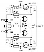
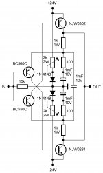
Or even less parts solution with thermal track output transistors, where tracking diodes have double function: bias input pair and compensates thermal drift. 😎
ah, I see it now...NJL thermaltrack 🙄 interesting, and they are even cheap 🙂
Hi all
From time to time i get asked what chassis and heatsink they should use.
So i plan to get a chassis folded with all holes laser Cut and painted.
It will be made for Dual and single supply.
It is intended for the TSSA V1.6 but could be for Any AMP
Is there Any interest for This?
- Sonny
From time to time i get asked what chassis and heatsink they should use.
So i plan to get a chassis folded with all holes laser Cut and painted.
It will be made for Dual and single supply.
It is intended for the TSSA V1.6 but could be for Any AMP
Is there Any interest for This?
- Sonny
Chassis
"A picture's worth a thousand words".
Ted
Hi all
From time to time i get asked what chassis and heatsink they should use.
So i plan to get a chassis folded with all holes laser Cut and painted.
It will be made for Dual and single supply.
It is intended for the TSSA V1.6 but could be for Any AMP
Is there Any interest for This?
- Sonny
"A picture's worth a thousand words".
Ted
"A picture's worth a thousand words".
Ted
And a pricing quotation so we know its Euro worth too.😀 Interested here.
Hi Sonny
Could use it for VSSA. Can you show us CAD drawings?
Regards L.C.
Sure. It will only be a matter of hole placement on the heatsinks.
I will let my friend Bert make the drawings.
This is an excellent amplifier and deserves an excellent chassis!
Depending on the cost, very interested.
Depending on the cost, very interested.
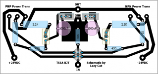
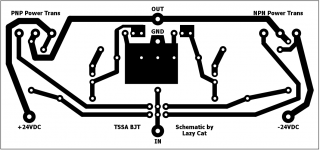
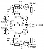
I hesitate to post this because I'm not sure if it's good or not. I've included three attachments. One of the Lazy Cat TSSA BJT circuit, second, of my pcb layout with component values and third, my pcb layout without component values. I layed out the pcb's in a program called DIYLayout Creator. I've been using it a lot for simple guitar stompboxes and small power amps. I know that I should just bite the bullet and learn Cadsoft Eagle. I was hoping someone could take a quick look and see where the glaring errors are or if I should just scrap the whole thing and use a better pcb editor. I've seen the layouts that Ales MM and a few other do here and there so good. (Beyond good). I just wanted to etch my own all bjt version of the TSSA and listen to it. You won't hurt my feelings if it stinks.
Tom
Tom
Attachments
Something like this, all BJT simplest. 😀
P.S. 1mF FB bridge cap can be also beneficial. 🙄
No, it is not bad at all.
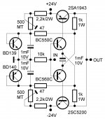
The same circuit could use njw0281/njw0302. With an higher idle in the input pair (10mA) and with good cooling it would be easy to do a class a amp with them also. Maybe even remove the collector resistors??!?!!! 😀
to not forget it
Attachments
Hi All.
I have made an powersupply design guide.
I know it is based on my modules but, I have added comment about fuse and wire dimensions.
I hope it is useful.
- Sonny
I have made an powersupply design guide.
I know it is based on my modules but, I have added comment about fuse and wire dimensions.
I hope it is useful.
- Sonny
Attachments
I hesitate to post this because I'm not sure if it's good or not. I've included three attachments. One of the Lazy Cat TSSA BJT circuit, second, of my pcb layout with component values and third, my pcb layout without component values. I layed out the pcb's in a program called DIYLayout Creator. I've been using it a lot for simple guitar stompboxes and small power amps. I know that I should just bite the bullet and learn Cadsoft Eagle. I was hoping someone could take a quick look and see where the glaring errors are or if I should just scrap the whole thing and use a better pcb editor. I've seen the layouts that Ales MM and a few other do here and there so good. (Beyond good). I just wanted to etch my own all bjt version of the TSSA and listen to it. You won't hurt my feelings if it stinks.
Tom
Wow, your design quite simple and nice compare to mine. (although a bit spacious IMO) Mine got complicated because i use thermal track OP transistor, so wired backed is messy, thus until now haven't build the circuit, had you built yours ?
IMO, the input stage line is a bit long/far, thus prone to interference (unless sufficient shielding of input stage path)
Last edited:
And its quite unnecessary to make the supply line long (between +- and OP transistor) as it will produce supply noise to signal line. Make it short by placing immediately beside transistor and avoid near small signal path.
Tom,
there is also a missing capacitor in between input transistor (550/560)
Tom,
there is also a missing capacitor in between input transistor (550/560)
Last edited:
- Home
- Amplifiers
- Solid State
- TSSA - The Simplest Symmetrical Amplifier