i do that all the time, no harm done, the tubes should be able to survive this...That sounds like poking the bear.
I don’t think I have the stomach for it.

i do that all the time, no harm done, the tubes should be able to survive this...
https://www.diyaudio.com/community/...mp-on-and-off-repeatedly-cause-damage.362912/
I built a TSE-II, following the instructions as well as I could.
If it were a point-to-point build, I would dig until it’s bulletproof, but there is a law of diminishing returns.
Your post #88 zip file does not open with your circuit parameters in it - perhaps best to take a screen shot of your circuit and results table and post that.
If you used a 5AR4 then it likely starts to conduct at the same time as signal valves start conducting - that means the start-up response from PSUD2 is not valid as you are not appropriately modelling the 5AR4 start up, or the signal valve loading. If you had used 5U4 then again the start-up would be different.
The other test you could do is to turn the amp off for a second or so, such that the B+ rail falls to effectively zero, but the cathodes are still hot, and then turn the amp back on - often referred to as a 'hot-start' event.
post #80 and #81 has the PSUD2 stuff
of course you do not do that willy-nilly, there are times that you need to do that, like during early days of testing and voicing where component size adjustments are made, when the amp has been normally set up steady, why will you do that? there is a context to everything.....there are reasons for doing things and if unsure of what you are about to do, then don't...this advise came from a tube guru when i was just starting here...I built a TSE-II, following the instructions as well as I could.
If it were a point-to-point build, I would dig until it’s bulletproof, but there is a law of diminishing returns
Last edited:
another unsolicited piece of advise when working with tubes or building many tube amps, get yourself a reasonably sized mains isolation transformers, it can save you from troubles, and a variac too...
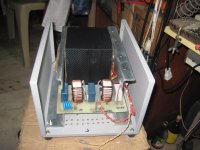
below is a homebrew 230:230vac isolation traffo good for 1kva
below is a homebrew 230:230vac isolation traffo good for 1kva
Attachments

Real/classic GZ34/5AR4s would heat faster, start conducting faster than typical output valves of the time. So even in the old days allowances had to be made for a B+ voltage surge at turn-on. Modern rectifiers labelled GZ34 or 5AR4 could be almost anything - I've seen fireworks from a variety of modern valve rectifiers. The Russian versions with zig-zag anodes (including some fancy stenciled-on names) seem to have more than their share of fireworks at turn-on. Chinese stuff I'd be afraid to try.
Why is it so hard to make a rectifier? Shouldn't be that hard, if you don't cheat.
All good fortune,
Chris
Why is it so hard to make a rectifier? Shouldn't be that hard, if you don't cheat.
All good fortune,
Chris
another unsolicited piece of advise when working with tubes or building many tube amps, get yourself a reasonably sized mains isolation transform
I really appreciate all advice!
Thank you.
Here is what has been done to the amp during this time on the bench:
- New mounting bracket for the large capacitor,
- 2 65 ohm 25W were added in series with each end of the HV winding to satisfy the “limiting resistance” requirement of the 5AR4 datasheet.
- R5 was replaced with a 3W part.
- R3 was lowered to 0.5 ohm.
- Tripled the number of venting holes in the top plate.
- Replaced all thermal pads on all chassis-mounted resistors.
- Rewired the input jacks.
I didn’t upgrade the reservoir capacitor to 500V from 450V because the 450V still looks great after 5 months of use in that amp and Nichicon says it can handle up to 200 cycles of surge current.
I didn’t upgrade the C5 capacitor to 500V from 450V because the 450V still looks great and the replacement had 40% more ripple listed in the datasheet.
Maybe these capacitors will come back to haunt me, but…
Listened for 1 hour tonight and this amp really sounds amazing.
Last edited:
Chinese stuff I'd be afraid to try
Actually, the Psvane holds the longevity record to date! It’s not saying much, though.
here's my little secret, i do not follow any schematics hook line and sinker, even my own designs, i look at the actual as-built amplifier, measure voltages and then listen, then i make adjustments to my liking when the amp is working already, but they are not majors, a little bit here and there...I really appreciate all advice!
Thank you.
Here is what has been done to the amp during this time on the bench:
- New mounting bracket for the large capacitor,
- 2 65 ohm 25W were added in series with each end of the HV winding to satisfy the “limiting resistance” requirement of the 5AR4 datasheet.
- R5 was replaced with a 3W part.
- R3 was lowered to 0.5 ohm.
- Tripled the number of venting holes in the top plate.
- Replaced all thermal pads on all chassis-mounted resistors.
- Rewired the input jacks.
I didn’t upgrade the reservoir capacitor to 500V from 450V because the 450V still looks great after 5 months of use in that amp and Nichicon says it can handle up to 200 cycles of surge current.
I didn’t upgrade the reservoir capacitor to 500V from 450V because the 450V still looks great and the replacement had 40% more ripple listed in the datasheet.
Maybe these capacitors will come back to haunt me, but…
Listened for 1 hour tonight and this amp really sounds amazing.
as to the choice between the 450vdc and 500vdc, as long as you do not pop any of them, that is fine...
80% of vdc rating is my guide but is not written in stone...i am trying to migrate to polypropylene psu filter caps in near future...
i do not put too much faith in simulations, after all the finished amplifier, its reliability and efficacy is all that matters in the end....
the supply of NOS is dwindling and if you find them, very costly...so now TV damper tubes are being gobbed up, they still sell very cheap, some in the U$1 per pop...Real/classic GZ34/5AR4s would heat faster, start conducting faster than typical output valves of the time. So even in the old days allowances had to be made for a B+ voltage surge at turn-on. Modern rectifiers labelled GZ34 or 5AR4 could be almost anything - I've seen fireworks from a variety of modern valve rectifiers. The Russian versions with zig-zag anodes (including some fancy stenciled-on names) seem to have more than their share of fireworks at turn-on. Chinese stuff I'd be afraid to try.
Why is it so hard to make a rectifier? Shouldn't be that hard, if you don't cheat.
All good fortune,
Chris
i purchased 4 of these and a friend two pcs, and all were good...it says Mullard, but coming out of China, i do not believe one bit....but hey it works....
https://www.lazada.com.ph/products/...z4p-5u4c-5ar4-rectifier-tube-i2289830885.html
and the reason why that is is probably due to the hybrid rectifier, two plates and two 1kv, 2A silicon diodes fed off a single secondary 330 volts ac. the lower voltage do not stress the plates as much as a 360-0-360 secondary would...i have never used such secondary's for over 20 years now...
Last edited:
yes, done this many times.....https://2img.net/h/tubes4hifi.com/TubeRectifier-DiodeMod.jpgThe yellow sheet mod has the benefit of extending that vintage (expensive to replace) goodness for perhaps a few more years. And for those using modern replacements, it can avoid unexpected fireworks. Win, win.
with this mod, the 3dg4 rectifier can be put to use..https://frank.pocnet.net/sheets/127/3/3DG4.pdf
Attachments
That was one of my original idea too, but it required cutting traces on the PCB, to keep the B- path the same as it is now.
Which reminds me…some Weber copper tops were also an option, but it would definitely require upgrading those capacitors and it would alter the balance of the power supply with regards to the rest of the circuit.
In essence, more a redesign than a repair.
In essence, more a redesign than a repair.
your b+ increases and so your amp will draw more power, but not very much...i made those ss rectifiers using discarded octal bases..Which reminds me…some Weber copper tops were also an option, but it would definitely require upgrading those capacitors and it would alter the balance of the power supply with regards to the rest of the circuit.
In essence, more a redesign than a repair.
My view was that the two traces from T1-4 and T1-5 would be cut, and new ss diodes inserted between those terminals and the valve base pads.That was one of my original idea too, but it required cutting traces on the PCB, to keep the B- path the same as it is now.
http://www.tubelab.com/images/AssemblyManualTubelabSE/Resistors_lo_res/up_toR29.jpg
My view was that the two traces from T1-4 and T1-5 would be cut, and new ss diodes inserted between those terminals and the valve base pads.
http://www.tubelab.com/images/AssemblyManualTubelabSE/Resistors_lo_res/up_toR29.jpg
This the latest board.
It looks like a practical mod would be to cut the traces (with enough gap to support 1.5kV) to pins 4 and 6 of the valve diode, and solder a 1N4007 across from each of the valve diode pads to the ss diode pads.

- Home
- Amplifiers
- Tubes / Valves
- TSE-II build and arcing rectifiers (mostly 5AR4 vacuum tubes, new issue)