Non-stepped, 150 mA current sink:

For both of these, you will notice I adjusted values of the parts based on actual measurements of the parts. Alas, I measured C1 and C2 in circuit, so it might be a different kind of wrong.
For both of these, you will notice I adjusted values of the parts based on actual measurements of the parts. Alas, I measured C1 and C2 in circuit, so it might be a different kind of wrong.
I hope most Hi Fi B+ CLC filters are designed so they do not resonate at either 1X or 2X the power mains frequency.
We are using the CLC pi filter to give smooth DC out.
We are not designing a CLC pi filter for a 7MHz radio amateur transmitter, that lets 7 MHz through, and severley attenuates the 14MHz and 21MHz harmonics from getting to the antenna.
41.5uF in series with 141.4uF, that resonates with 10Henrys does not resonate anywhere near to 1X, 2X, or even 3X the power mains frequency.
This one resonates at approximately 9Hz.
Last edited:
I hope most Hi Fi B+ CLC filters are designed so they do not resonate at either 1X or 2X the power mains frequency.
We are using the CLC pi filter to give smooth DC out.
We are not designing a CLC pi filter for a 7MHz radio amateur transmitter, that lets 7 MHz through, and severley attenuates the 14MHz and 21MHz harmonics from getting to the antenna.
41.5uF in series with 141.4uF, that resonates with 10Henrys does not resonate anywhere near to 1X, 2X, or even 3X the power mains frequency.
This one resonates at approximately 9Hz.
Do you know if PSUD2 would warn against such unfortunate choices?
Is there any other tools you know that could help guide the design process?
All of these values were carefully selected by George, based on theory and lots of experimentation, so I’m sure they are practical and effective outside the simulation world, but I still find a tool like PSUD2 very useful.

The thing is, the power transformer secondary winding DC resistance and inductance are important parts of this tuned circuit. George designed this CLC pi filter for the transformer he specified. You've deviated from the design by choosing a different power transformer, so you need to check your redesign. It's not so bad. It's all part of the fun.Do you know if PSUD2 would warn against such unfortunate choices?
Is there any other tools you know that could help guide the design process?
All of these values were carefully selected by George, based on theory and lots of experimentation, so I’m sure they are practical and effective outside the simulation world, but I still find a tool like PSUD2 very useful.
If you want to post your PSUD2 file, maybe those of us who play with these kinds of things will give it a go and post what we find.
Otherwise, we'll have to use mathematics! But I figure computers are for performing computations, so let 'em have at it.
We do need to be very careful about the data we enter into the machine. Can you post the DC resistance of each of the power transformer secondary windings from center tap, and the DC resistance of the primary winding (if possible)? Did you (CAREFULLY!) measure the off-load (unloaded) voltages of the transformer with 120V AC applied to the transformer primary? We also want the DC resistance of the choke. All that should be entered into PSUD2 so it knows what it's calculating from. Otherwise the results in PSUD2 can't be trusted.
i never used PSUD2, ever....
It's a fantastic piece of software.
The thing is, the power transformer secondary winding DC resistance and inductance are important parts of this tuned circuit. George designed this CLC pi filter for the transformer he specified. You've deviated from the design by choosing a different power transformer, so you need to check your redesign. It's not so bad. It's all part of the fun.
If you want to post your PSUD2 file, maybe those of us who play with these kinds of things will give it a go and post what we find.
Otherwise, we'll have to use mathematics! But I figure computers are for performing computations, so let 'em have at it.
We do need to be very careful about the data we enter into the machine. Can you post the DC resistance of each of the power transformer secondary windings from center tap, and the DC resistance of the primary winding (if possible)? Did you (CAREFULLY!) measure the off-load (unloaded) voltages of the transformer with 120V AC applied to the transformer primary? We also want the DC resistance of the choke. All that should be entered into PSUD2 so it knows what it's calculating from. Otherwise the results in PSUD2 can't be trusted.
Yep, measured all that and entered all that. The simulations above were based on actual measurements of each part.
I’ll post the file when I am back at my computer.
i am sure it is...even if i never used it..It's a fantastic piece of software.
Thanks. I ran it, and I see what you see. It looks like there is voltage overshoot as the 5AR4 warms up, up to and possibly beyond 450V, but it settles down quickly as the 300B warms up and draws current. B+ voltage appears to settle at roughly 380V with 150mA drawn. Ripple looks like only about 37mV, which is quite good, no?
What exactly is the problem people are seeing? As far as I can tell, the 9Hz oscillation happens only as the 5AR4 is warming up. Using the stepped current tap feature I don't see an oscillation in the step (after the 5AR4 has warmed up and the caps have charged).
What exactly is the problem people are seeing? As far as I can tell, the 9Hz oscillation happens only as the 5AR4 is warming up. Using the stepped current tap feature I don't see an oscillation in the step (after the 5AR4 has warmed up and the caps have charged).
Last edited:
Thanks. I ran it, and I see what you see. It looks like there is voltage overshoot as the 5AR4 warms up, up to and possibly beyond 450V, but it settles down quickly as the 300B warms up and draws current. B+ voltage appears to settle at roughly 380V with 150mA drawn. Ripple looks like only about 37mV, which is quite good,
Yes, I think it’s quite good.
I think I just need to decide if I want to upgrade C4 and C5 to 500VDC parts.
I kind of think it’s overkill, but…
Do not use your 10X probe and oscilloscope to look at those B+ power-up voltages.
Not with your scope input set to DC coupling.
Not with your scope input set to AC coupling.
Instead, $pend the money, and get a proper Tektronix P5100 100X probe.
It will $ave you the repair of your scope input circuitry (or more likely the required replacement of your scope).
The P5100 is properly compensated to go to 250MHz (complex circuit, "coax" lead wire, etc.)
But for a simple understanding of the protection ability, it has a 9Meg series resistor, 110k parallel resistor to ground (in parallel with your scope 1Meg resistor).
It will protect all of the scope input circuitry, even that 300V or 600V AC coupling cap.
Have fun measuring a real circuit, so you can verify the results of the software.
this is the only instrument that i use to monitor tube amplifier startups, sometime i will make a video of it...
nothing beats real time resting on a real amp, getting real time results...now when things have settled on your amps and properly warmed up, measurements of voltage, ripples and some can proceed....
nothing beats real time resting on a real amp, getting real time results...now when things have settled on your amps and properly warmed up, measurements of voltage, ripples and some can proceed....
Attachments
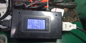
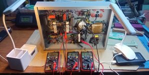
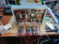
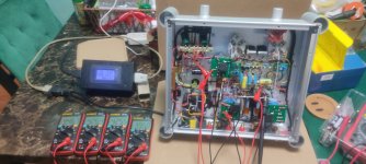
Beefier resistors arrived today and were promptly installed.
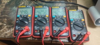
I had 4 multimeters in various places and I did not see any of the big voltage spikes PSUD2 promised.
I did see the effect of the new series resistors, though, which took down B+ some. Plus AV voltage is down today again, due to the heat waves.
I should get a regulator.
I’ll give it a listen now.
I had 4 multimeters in various places and I did not see any of the big voltage spikes PSUD2 promised.
I did see the effect of the new series resistors, though, which took down B+ some. Plus AV voltage is down today again, due to the heat waves.
I should get a regulator.
I’ll give it a listen now.
Last edited:
Tektronix Digital Scopes can capture what preceded the triggering event, as well as after the triggering event.
Real Time, yes.
My humble inexpensive Tektronix digital scope does that.
If I describe a Tektronix Real Time Spectrum Analyzer, will anybody understand?
Most will not, so here is a Partial explanation:
A real time transmitter receiver is pointed at the Moon.
The customer speaks into the microphone, "Hello Test, 1, 2, 3"
2-1/2 seconds later the customer hears: "Hello Test, 1, 2, 3"
That Is real time (even though it is delayed by 2-1/2 seconds).
A Non-real-time transmitter receiver is pointed at the Moon.
The customer speaks into the microphone, "Hello Test, 1, 2, 3"
2-1/2 seconds later the customer hears: "Hello Test, __ __ 3"
That is missing the 1, and is missing the 2,
That is Not real time.
And there you have it.
Last edited:
You are saying a multimeter would not capture voltage spikes that may occur during the first few cycles of a power-up scenario.
I suspected as much, but I gotta do with what I have.
I think the amp is in a much better place now, but time will tell.
I suspected as much, but I gotta do with what I have.
I think the amp is in a much better place now, but time will tell.
transients are like what? 3 electrical cycles, maybe 5, on a 60hz line, that is a mere 17 m-secs, too fast for a dmm, but the scope will capture...5 periods of 17 m-secs is still to short at 83msecs...You are saying a multimeter would not capture voltage spikes that may occur during the first few cycles of a power-up scenario.
when you are building tube amps, it pays to have several dmm's to measure voltages at once..
Attachments
Last edited:
Your post #88 zip file does not open with your circuit parameters in it - perhaps best to take a screen shot of your circuit and results table and post that.I had 4 multimeters in various places and I did not see any of the big voltage spikes PSUD2 promised.
If you used a 5AR4 then it likely starts to conduct at the same time as signal valves start conducting - that means the start-up response from PSUD2 is not valid as you are not appropriately modelling the 5AR4 start up, or the signal valve loading. If you had used 5U4 then again the start-up would be different.
The other test you could do is to turn the amp off for a second or so, such that the B+ rail falls to effectively zero, but the cathodes are still hot, and then turn the amp back on - often referred to as a 'hot-start' event.
the directly heated rectifiers like the 5y3/5u4 types are quick acting as it conducts as soon af filaments get warmed up, the ICH cathode types like the 5ar4 are different as there is a delay in the b+ buildup,the cathodes have to be heated up first...
The other test you could do is to turn the amp off for a second or so, such that the B+ rail falls to effectively zero, but the cathodes are still hot, and then turn the amp back on - often referred to as a 'hot-start' event.
That sounds like poking the bear.
I don’t think I have the stomach for it.
- Home
- Amplifiers
- Tubes / Valves
- TSE-II build and arcing rectifiers (mostly 5AR4 vacuum tubes, new issue)