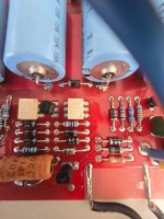
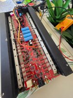
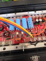
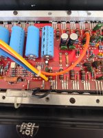
Hi everyone, as per title, I need some help in trying to resurrect the amp. was working perfectly until, unfortunately, the speaker terminals, on the speaker side got loose and shorted. massive fry up the PWM session, 3 fried original 2N6488. anyway, opened it up and found more were not in good shape and once removed the bars, I had to go full strip down.
Out of the total 25 2N5488 I could only test 8 good and out of the 2N6491 1, most of the latter broke when trying to remove from the bar, despite using Perry's suggested method. to cut the story short, I removed all from the PWM and output, including the SF163/A and the LM317T/337T. went to local electronics shop and got BD911 to replace the 2N6488 and BD912 to replace the PNP 2N6491.
SF163/A came out good so put them back.
MSPA06 tested on board and all look good.
MCT2V octocoupler also tested on board and seems good. anyway, I wne on and read in the past I could add power with just a barebone structure in place, so I put back the BD911 driven by the MSPA06 for the gate drive and 2x BD911 per rain in the PWM, SF163/A and powerd up with a 12v bulb as safety.
Didn't smoke anything and I got VAC out of the secondary of the main toroid and VDC aout of the center pin of the SF163/A, I only got 1.7 VDC on the SF163 and -2 VDC of the SF163A, this using the driver output GND as reference. also, REM doesn't seem to do anything as soon as I power up the amp goes on.
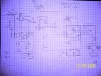
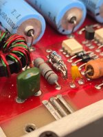
I tried Perry's trick or desoldering one leg of the thermal protection, but that doesn't seem to change anything on the REM circuit. so I checked again the octocoupler on the left, the R and the diodes, and the 2 MPSA06. all seems good by the reading when checked in diode mode. i have drawn the schematic as best i could, and i ended up with the exact same diagram of what was posted here already. i need some help troubleshooting this nice amp. I know and I'm sure there are better sounding amps out there, but I just love the form factor, the tone, and the looks.
i have a switch to enable REM ON/OFF and I can see 12V or 0 when flicking it.
Power led also not lighting up
original schematics credit to 90scaraudio from this thread: https://www.diyaudio.com/community/threads/orion-2150gx-repair-help.220408/
Out of the total 25 2N5488 I could only test 8 good and out of the 2N6491 1, most of the latter broke when trying to remove from the bar, despite using Perry's suggested method. to cut the story short, I removed all from the PWM and output, including the SF163/A and the LM317T/337T. went to local electronics shop and got BD911 to replace the 2N6488 and BD912 to replace the PNP 2N6491.
SF163/A came out good so put them back.
MSPA06 tested on board and all look good.
MCT2V octocoupler also tested on board and seems good. anyway, I wne on and read in the past I could add power with just a barebone structure in place, so I put back the BD911 driven by the MSPA06 for the gate drive and 2x BD911 per rain in the PWM, SF163/A and powerd up with a 12v bulb as safety.
Didn't smoke anything and I got VAC out of the secondary of the main toroid and VDC aout of the center pin of the SF163/A, I only got 1.7 VDC on the SF163 and -2 VDC of the SF163A, this using the driver output GND as reference. also, REM doesn't seem to do anything as soon as I power up the amp goes on.
I tried Perry's trick or desoldering one leg of the thermal protection, but that doesn't seem to change anything on the REM circuit. so I checked again the octocoupler on the left, the R and the diodes, and the 2 MPSA06. all seems good by the reading when checked in diode mode. i have drawn the schematic as best i could, and i ended up with the exact same diagram of what was posted here already. i need some help troubleshooting this nice amp. I know and I'm sure there are better sounding amps out there, but I just love the form factor, the tone, and the looks.
i have a switch to enable REM ON/OFF and I can see 12V or 0 when flicking it.
Power led also not lighting up
original schematics credit to 90scaraudio from this thread: https://www.diyaudio.com/community/threads/orion-2150gx-repair-help.220408/
Attachments
-
 20250404_095059.jpg471.8 KB · Views: 54
 -
 20250404_131605.jpg653.7 KB · Views: 51
 -
 20250404_131612.jpg521.6 KB · Views: 50
 -
 20250404_131615.jpg530.8 KB · Views: 51
 -
 20250404_131616.jpg475.3 KB · Views: 48
 -
 20250404_131626.jpg536.8 KB · Views: 49
 -
 20250404_131623.jpg514.9 KB · Views: 56
 -
 2150gx.JPG464.9 KB · Views: 58
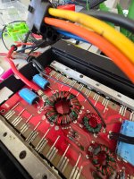
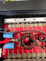
The self-oscillating amps didn't like resistance in the B+ line and most won't power up unless powered directly without limiting. If you want to protect it, clamp all transistors tightly to the heatsink and insert a 15 amp fuse in the B+ line.
Use high temperature silicone rubber tape instead of the double-sided tape.
Use high temperature silicone rubber tape instead of the double-sided tape.
Attachments

Last edited:
thaks Perry, always super helpfull. sorry, didn't mention, amp board is connected and transistor clamped down. So i will test withouth bulb but a 15A fuse on the B+
ok, with a 15A fuse on the B+, applied power and nothing smoked.
readings:
REM ON
Pin 2 of SF163 +39.7 VDC
Pin 2 of SF163A -39.7 VDC
REM OFF
Pin 2 SF163 +0.9 VDC
Pin 2 SF163A -0.9 VDC
are these expected values?
ran for about 10 minutes to double checks reading and not heat building up on the transistors
readings:
REM ON
Pin 2 of SF163 +39.7 VDC
Pin 2 of SF163A -39.7 VDC
REM OFF
Pin 2 SF163 +0.9 VDC
Pin 2 SF163A -0.9 VDC
are these expected values?
ran for about 10 minutes to double checks reading and not heat building up on the transistors
yes, read all about it in the last couple of days and bumped onto this advise. including metal brush to remove the original from factory 😉The self-oscillating amps didn't like resistance in the B+ line and most won't power up unless powered directly without limiting. If you want to protect it, clamp all transistors tightly to the heatsink and insert a 15 amp fuse in the B+ line.
Use high temperature silicone rubber tape instead of the double-sided tape.

You asked about the voltage. The regulator has a Zener that controls the voltage. Find the number on that Zener. That should give you the rail voltage.

Well, if that's the regulator Zener, the regulator doesn't seem to be working. ±40v isn't catastrophic. If you want to troubleshoot, check the 2N6488 and the MPSA06 as well as measuring the voltage across that parallel pair and the Zener beneath the resistor.
sorry Perry, just to be sure we are on the same page, the +-39 VDC were measuresd at the pin 2 of the fast swtiching dual diodes, after they have rectified the AC coming from the secondary of the main toroid.
did not measure the V on the driver winding
did not measure the V on the driver winding
The regulation is for the voltage feeding the output transistors. That's the voltage from the output (center terminal) of the main rectifiers.
so, i powered up the amp again, and probed the Zener 1N4751A rated 30V with Red on the cathode and black on the anode
READINGS:
REM ON 26.3 VDC
REM OF 0.6 VDC
READINGS:
REM ON 26.3 VDC
REM OF 0.6 VDC
Unless specifically noted, the only voltages that are important are with remote voltage applied.
If they read 26v, the regulators is definitely not working... assuming that those are the regulator Zeners shown in the diagram.
If they read 26v, the regulators is definitely not working... assuming that those are the regulator Zeners shown in the diagram.
yes, the Zener in the path betweeen the tertiary winding and the MPSA06 like in the schematic provided
UPDATE: in a nutshel, BD911 is not a replacement for 2N6488 in the PWM.
I had 8 left from the tsunami, put them back 3 each rail, 1 as gate driver and BOOM, back on the game with +34.4VDC at the Zener (cathode side), 32.5 after 10 minutes on idle.
Next issue now, with the BD911 it would feel the REM ON/OFF, now it won't.
Ideas? i checked already the thermal sensor and OL in diode mode
Next issue now, with the BD911 it would feel the REM ON/OFF, now it won't.
^^^ Are you sure this is what you meant to write?
P.S., PAM, not PWM.
^^^ Are you sure this is what you meant to write?
P.S., PAM, not PWM.
UPDDATE: REM functionality narrowed down to leaky octocoupler. REM OFF pin 1 0 VDC, pin 3 0.08 VDC, Pin 4 12.5 VDC. result octo stuck open
- Home
- General Interest
- Car Audio
- trying to resurrect an Orion 2150GX after massive short