yes, exactly that. with the BD911 in the PAM it would switch on and off from REM. with the original JSE2889 AKA 2N6488 wouldn't.Next issue now, with the BD911 it would feel the REM ON/OFF, now it won't.
^^^ Are you sure this is what you meant to write?
P.S., PAM, not PWM.
once I have replaced the octo i can confirm that or not. not have looked at the output stage.
i need to source the transistor now as the full set of BD911/912 is going back to the shop
i need to source the transistor now as the full set of BD911/912 is going back to the shop
MANY people have used the BD transistors in the output stage.
Don't expect any electronics distributor to accept returns on electronic components.
Don't wait on the optocoupler if switching on/off is the only problem. Bridge the output of it to force the supply to power up so you can troubleshoot the audio stage.
Don't expect any electronics distributor to accept returns on electronic components.
Don't wait on the optocoupler if switching on/off is the only problem. Bridge the output of it to force the supply to power up so you can troubleshoot the audio stage.
If the BD's work in the output stage without change any R value then I can go ahead and solder them on the board so I can assess if there is any damage to the output stage
I know that people in Europe generally use them. That said, I can't know if you purchased genuine parts from a reputable/authorized distributor. If they are genuine parts, they should be drop-in replacements.
Very old standing reputable local shop, the owner himself is analogue ❣️so shouldn't be an issue of counterfeit parts
UPDATE:
installed BD911/BD912 in the output session.
fired up and no issues when idling, no heat building up, both PAM and output stage cold
I have 0 VDC at speaker terminals in Idle
Plugged in RCA cables and fed with 1khz 0db sine wave, Source mobile connected to BT/DAC connected via RCA to amp
I have loaded the amp with an old mid 4 ohms
Both Channels play at same level, no major or noticeable difference, but a small audible tik every 5/6 secs
No sine wave playing, audible ground noise
No RCA, no ground noise in neither of the channels
tested with laptop as source,
same 1khz sine wave, NO ground noise and NO clicks
i don't have an oscilliscope I'm afraid to do any further diagnose.
amps is still running cold
once I have the full set of 2N6488 for the PAM i can probably say repaired, till then open guts
Last edited:
There seems to be some confusion with the terminology. I hope this isn't considered to be contamination of the thread.
Car amps use switching power supplies to boost voltage.
There are two general types, regulated and unregulated.
Unregulated supplies have an output voltage that follows the B+ supply voltage. The supply voltage is greater than B+ but it's a multiple and varies with the B+.
Regulated supplies have two general types of regulation. The most popular, by far, is the PWM regulation. This type varies the width of the pulses that drive the transformer. Wider pulses generate more output. The wider pulses are used when there is more demand from the audio output stage or when the B+ voltage drops. The regulation holds the rail voltage to the target voltage.
Orion, PPI, a few other use (used) PAM (Pulse Amplitude Modulation). It's not quite as efficient but has some advantages in some situations. The PAM circuits drive the FET gates with varying amplitude signals. When there is greater need for output, the drive signal amplitude is increased. This leaves the FETs working in their linear region but only at lower power so, while it's inefficient, it's only inefficient at lower power.
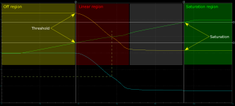
Linear region... For FETs to work efficiently, they have to be drive into saturation. Some may use a different term. Saturation is more properly used for bipolar transistors. Right or wrong, saturation (for this description) means that the FET is drive with a strong enough signal (generally, 10v is considered the 'sweet spot') to allow them to conduct as well, as efficiently, as they possibly can. This means that they will have the minimum voltage across their drain and source when passing the highest current. This results in the lowest power dissipation. In linear mode, they are not working efficiently because their gate voltage isn't driving them into saturation. This results in greater power dissipation/heating. The attached shows what was described. The green line is gate voltage. The yellow line is the drain voltage. Note how the drain voltage goes lower as the gate rises through the region marked 'linear'.
So... calling the power supply a PWM or a PAM is a bit unusual. The power supply is typically referred to as simply a power supply. Only when you are referring to the type of regulation, specifically, would you use PWM or PAM.
For your amp, try a different signal source.
Car amps use switching power supplies to boost voltage.
There are two general types, regulated and unregulated.
Unregulated supplies have an output voltage that follows the B+ supply voltage. The supply voltage is greater than B+ but it's a multiple and varies with the B+.
Regulated supplies have two general types of regulation. The most popular, by far, is the PWM regulation. This type varies the width of the pulses that drive the transformer. Wider pulses generate more output. The wider pulses are used when there is more demand from the audio output stage or when the B+ voltage drops. The regulation holds the rail voltage to the target voltage.
Orion, PPI, a few other use (used) PAM (Pulse Amplitude Modulation). It's not quite as efficient but has some advantages in some situations. The PAM circuits drive the FET gates with varying amplitude signals. When there is greater need for output, the drive signal amplitude is increased. This leaves the FETs working in their linear region but only at lower power so, while it's inefficient, it's only inefficient at lower power.
Linear region... For FETs to work efficiently, they have to be drive into saturation. Some may use a different term. Saturation is more properly used for bipolar transistors. Right or wrong, saturation (for this description) means that the FET is drive with a strong enough signal (generally, 10v is considered the 'sweet spot') to allow them to conduct as well, as efficiently, as they possibly can. This means that they will have the minimum voltage across their drain and source when passing the highest current. This results in the lowest power dissipation. In linear mode, they are not working efficiently because their gate voltage isn't driving them into saturation. This results in greater power dissipation/heating. The attached shows what was described. The green line is gate voltage. The yellow line is the drain voltage. Note how the drain voltage goes lower as the gate rises through the region marked 'linear'.
So... calling the power supply a PWM or a PAM is a bit unusual. The power supply is typically referred to as simply a power supply. Only when you are referring to the type of regulation, specifically, would you use PWM or PAM.
For your amp, try a different signal source.
Attachments
thank you for the update. makes more sense now.
Found that I do not have phanton +-15VDC to the opam's going to trace back from the 2nd octocoupler
Found that I do not have phanton +-15VDC to the opam's going to trace back from the 2nd octocoupler
didn't measure, what i did measure is the VDC at pin 2 of the LM317/337
LM317 has +13.4 VDC
LM337 has -0.01 VDC
will have to investigate this part of the amp

LM317 has +13.4 VDC
LM337 has -0.01 VDC
will have to investigate this part of the amp
UPDATE:
REM switch does actually do something on OPamps (NE5534).
With REM OFF i have 1.1DCV between Pin 4 V- and Pin 7 V+
with REM on i have 26.5 DCV
with REM on, the 1khz sine wave is definitively ampliefied.
all seems to be ok from my POV
REM switch does actually do something on OPamps (NE5534).
With REM OFF i have 1.1DCV between Pin 4 V- and Pin 7 V+
with REM on i have 26.5 DCV
with REM on, the 1khz sine wave is definitively ampliefied.
all seems to be ok from my POV
- Home
- General Interest
- Car Audio
- trying to resurrect an Orion 2150GX after massive short