This is true for this style piezo. But for the larger style ( e.g. https://www.parts-express.com/GRS-P...-Tweeter-Similar-to-KSN102-292-444?quantity=1 ) they come apart more completely. Unscrew, and the horn / phase plug comes off as one piece, and then the piezo element + diaphragm come off, and the back comes off as a cap. More places to potentially leak air, but allows easy access to the back of the piezo and diaphragm. I considered unsoldering mine to reach the back but figured I would melt the plastic housing. I've already picked up some of these larger ones to experiment with. In addition to potentially being more leaky, they also seem to have more molding flash on the plastic parts. But more friendly to mods, and the plastic is thicker.In former times I used to dampen the back side and even putting a second layer of alu foil on the backside.
You have to unsolder the wiring for that gently putting the paper cone up/out without deforming it.
I see the foam and rubber dampers on the diagram in post 2. If anyone has pictures or more detail about these parts I'd love to know about it. Apart from dryer lint 😉 which actually seems like a really good density for this sort of thing. I've been considering what sort of material (and how to attach) to use for the back side of the piezo element.Even adding a rubber damper to the Piezo like in the early Motorola piezos is worth a try.
Yes, I think unfiltered the LF signal doesn't make sound but still uses up the deformation range of the piezo element.What I like most with piezos that if filtered properly at least with minimal crossover of 6db they lose their nervous sound everyone experiences with the raw drivers.
Yes, but it depends on the inductance. For the same core: higher inductance = lover rated amperage (saturation)So perhaps it is core saturation which is the limiting factor?
You don't need them for a tweeter filter - they are more expensive. If you are willing to pay more, air core inductor is much better.I wonder if there is a slightly larger ferrite core version available...
With the same small ferrite core, rated amperage is between 0.77 and 0.85 A for inductances between 0.22 mH and 0.33 mH.
0.33 mH, 850 mA, $0.68
https://www.digikey.com/en/products/detail/bourns-inc/RLB0913-331K/6677227
0.27 mH, 770 mA, $0.42
https://www.digikey.com/en/products/detail/bourns-inc/RLB0914-271KL/2352778
0.22 mH, 800 mA, $0.42
https://www.digikey.com/en/products/detail/bourns-inc/RLB0914-221KL/2352777
Last edited:
So, no further development, but I've learned a little more about phase in REW. I had thought that 'compute minimum phase' would remove the distance delay in the phase of my measurement. But I guess not? Here is the measurement with phase as taken...

and the notes that came up with the measurement say it has a delay of 3.1342 ms / 1.075 m / 3 ft 6.3 in. This is with a 2 channel capture with a mic and a timing ref channel. I left the delays in for my XSim work.
I can go to "actions" (gear icon, above graph on R) and select "offset t=0" and change that 0 to equal the time reported...

And now I see a phase flip at the XO point, which was what I had expected. And I think this is "phase" for the speaker.
But there is (after REW generates it) Minimum Phase and Excess Phase. I had kinda thought a speaker was a minimum phase system, so I am a bit confused about what these things mean WRT a measurement.
Min phase -

Excess phase -

Hmmmmmm... I've read a bit about it, but don't quite have it figured out. I'll continue to look for an explanation that makes sense to me.
and the notes that came up with the measurement say it has a delay of 3.1342 ms / 1.075 m / 3 ft 6.3 in. This is with a 2 channel capture with a mic and a timing ref channel. I left the delays in for my XSim work.
I can go to "actions" (gear icon, above graph on R) and select "offset t=0" and change that 0 to equal the time reported...
And now I see a phase flip at the XO point, which was what I had expected. And I think this is "phase" for the speaker.
But there is (after REW generates it) Minimum Phase and Excess Phase. I had kinda thought a speaker was a minimum phase system, so I am a bit confused about what these things mean WRT a measurement.
Min phase -
Excess phase -
Hmmmmmm... I've read a bit about it, but don't quite have it figured out. I'll continue to look for an explanation that makes sense to me.
I've no measurements on this one - but it sounds really good and better than a 5x KSN1016 array on stepup
One KSN1016 Motorola) on the 5 watt tap of a 25v matching transformer. The 8 ohm tap is used for the primary and has 7.2 ohm/100uH Zobel - - crossover is all I have ~1.3uF cap. The wideband in the little Karlson K12 is Celestion's K12H-200TC. There's 22 ohms in series with the piezo.
One KSN1016 Motorola) on the 5 watt tap of a 25v matching transformer. The 8 ohm tap is used for the primary and has 7.2 ohm/100uH Zobel - - crossover is all I have ~1.3uF cap. The wideband in the little Karlson K12 is Celestion's K12H-200TC. There's 22 ohms in series with the piezo.
Attachments

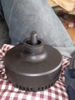
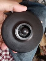
can me tell someone what kind of piezo tweeter this "professional" piezo from Mc Gee is?
What does the coil do?
Anyone knows its schematic?
There is a 4.7uF nonpolar 50v cap in line, the coil is in parallel?

I measured it with white noise and Spectroid app without horn

drops like a stone at 4khz
What does the coil do?
Anyone knows its schematic?
There is a 4.7uF nonpolar 50v cap in line, the coil is in parallel?
I measured it with white noise and Spectroid app without horn
drops like a stone at 4khz
Attachments
with a big horn 42cm x 18cm it only does a few db more at 2khz.
Its a joke.


for the horns I bought real drivers as this piezo does no job in it
Its a joke.
for the horns I bought real drivers as this piezo does no job in it
If I find time I will measure the tweeter without this step up former and with.
What is the ratio of the up step?
It lowers the high impedance and you get more voltage into the piezo?
What is the ratio of the up step?
It lowers the high impedance and you get more voltage into the piezo?
Yes.you get more voltage into the piezo?
I don't know the step-up ratio. It may be different for different kinds of piezo discs.
Was looking the web for piezo drivers with a bigger paper cone for horns but did not find any.
Still if the piezo disc cannot generate a travel the radiating area should become bigger - like 7, 8 or 10cm in diameter.
But I did not find anything.
The Monacor MPT-142 is a simple piezo driver (92db).
The Mc Gee HLQ-02 (102db) I showed some posts before has uniquely the step up air coil which certainly gets more signal to the piezo.
Read that my big Mc Gee HL1018 plastic horns are criticized for to have a not well designed throat with a jump (=not smooth transition) in the beginning from 2.5cm to 4cm. There are threads about modifications for that.
But the weakness of spl around 1khz is due to the piezo drivers who simply make no cone travel.
Real tweeter drivers for horns can suffer from lack of cone travel, too.
The Mc Gee Comp50 with titanium 51mm metal cone has only a stiff suspension of the same material. Now I read they use it due to distortion problems not below 1700hz in PA use. For home hifi not below 1100hz.
The big HL1018 horn can work from 800hz up with a proper driver with a mellow surround.
As I like the transient and crisp response of piezos I was thinking of DIY making my own bigger piezo diaphragm.
Some adapt small fullrange driver to the HL1018 horn cutting the throat to fit the aperture.
Could be that the 4.7uF cap should be bigger.
If changed than for a foil type and bigger like 6.8 or 10uF.
If changed than for a foil type and bigger like 6.8 or 10uF.
I have seen some of the 1188 type piezos claim they can operate to pretty low frequency.
https://www.parts-express.com/GRS-PZ1188-Piezo-Horn-Driver-Similar-to-KSN1188A-292-450?quantity=1
800 Hz? I'm not sure if I believe it. But I don't have one, so I don't know.
I've wondered what it would take to lower response.
I haven't tried any of those things myself...
https://www.parts-express.com/GRS-PZ1188-Piezo-Horn-Driver-Similar-to-KSN1188A-292-450?quantity=1
800 Hz? I'm not sure if I believe it. But I don't have one, so I don't know.
I've wondered what it would take to lower response.
- soften the surround area of the diaphragm, maybe pokes with a needle or work it to soften it? Probably easy to screw up the unit!
- larger rear chamber? holes in the plastic, if it doesn't share volume with a woofer?
- mass on the back of the piezo element? It isn't pushing against any rigid structure, so more inertia might give it more push.
I haven't tried any of those things myself...
That 33ohm resistor will actually cause very high frequency roll-off due to the natural capacitance of the Piezo driver.It doesn't have to be big, if you include series resistor with the inductor. That "dumping" resistor is crucial (6.8 ohms here), see my "ultimate" crossover for Motorola KSN 1005A:
https://www.diyaudio.com/community/threads/to-piezo-or-not-to-piezo.310934/page-2#post-5162616
View attachment 1299017
Blue: Motorola KSN 1005A
Green: with "ultimate crossover"
View attachment 1299021
If you replace the 33ohms with a .1mH inductor you will be amazed at the very high frequency response 🙂
Thats the thread on the HL1018 horn
https://www.diy-hifi-forum.eu/forum...ee-HL-1018&s=2c28c0a3bbff04e3ff4676a733bebdd1
Here an image of what the horn can do with a "normal" driver (not piezo). Could be used easily from 800 hz on IF the driver can do it with low distortion. The acoustical knee after linearization would even allow for 450 hz. Blue line is for modified throat with a better transition.
Piezos do not have that rising efficiency with the horn like drivers which can make a travel.
Just for some extra info. >
https://www.diyaudio.com/community/...tweeter-piezo-tweeter-revisited.399363/latest
https://www.diyaudio.com/community/...tweeter-piezo-tweeter-revisited.399363/latest
@Mister Audio
A hint to the original Motorola production? Like it. They have also plastic cones which certainly outperform the paper cone type.
A hint to the original Motorola production? Like it. They have also plastic cones which certainly outperform the paper cone type.
This one looks pretty much like plastic cone - its phenolic type to be weather proof

Attachments
Last edited:
- Home
- Loudspeakers
- Multi-Way
- Trying to get the best out of cheapo piezos