Hi so this is my first time asking for advice on here, ive been a lurker for a while but im literally at my wits end with my speaker build, so im hoping someone can help me to finally finish this.
Ive had some really great help from someone on another forum, i wouldnt have gotten this far without him tbh but i think hes too busy at the minute to walk me through everything, and i hate to keep repeatedly bothering someone with my problems
So basically ive designed an mtm using two pc83-4 woofers and a td20f-4 tweeter for use in my home cinema system, i wired the woofers in series and connected the tweeter in parallel. I bought the dats system and the omnimic so that i could take my own in box measurements but had a big issue with that at the start, my computer was affecting the tracks that were played and giving me false readings, that is sorted now, i think. My measurement method was as follows,
I set the mic 16" away on the centre of the tweeter, then took 3 sets of measurements without moving anything or changing the amp volume, they were the tweeter playing alone, then the woofers in series, then the woofers and the tweeter all together. I took those to find the z offset in xsim and it turns out its around 0.7. My issue now is that ive been advised that i should use the 'woofer in series' frd file in xsim to create the crossover, but im literally so confused by that, How do i add the frd files of two woofers playing in series into two separate simulated drivers in xsim? Every time i try it i end up with 16ohms impedance because it thinks each simulated driver is 8 ohms, but theyre not, i need them to read as 4 ohms. I cant continue with the crossover until i figure this out, i managed to get somewhere with it using the frd i created when i measured just one of the woofers instead of them in series, as i can add the files in the same way i do with the downloaded manufacturers frd files but like i said ive been advised to do it differently. I apologize if this post is a bit confusing, but id really appreciate any help with this and the crossover i eventually plan to design.
You don't have to struggle so much. Just buy a kit from a designer who has lots of experience and has created something that will really sound good for you.
If you want a small MTM one suggestion is the very inexpensive Overnight Sensations MTM designed by Paul Carmody. Only $118 each at Meniscus Audio. Other good choices also in that price range can be found at Madisound, Parts Express, and diysoundgroup.
If you want a small MTM one suggestion is the very inexpensive Overnight Sensations MTM designed by Paul Carmody. Only $118 each at Meniscus Audio. Other good choices also in that price range can be found at Madisound, Parts Express, and diysoundgroup.
Thanks for the reply, im not the type of person who does that though tbh, i prefer to make things for myself, im a fabricator by trade so i enjoy making things from scratch. Ive made a few speakers already but i chose to start off with full range drivers, this is my first attempt at a crossover and i really want to understand how its done as i plan to make more in the future. Plus i already have the speakers in their boxes and running on the av reciever. I made 5 for my surround sound and a subwoofer, they have been working fine for a few month now as i used full range drivers for the woofers, added a baffle step and just left the tweeter unconnected until i figured out the crossover etc.
Dayton Audio - PC83-4 3" Full-Range Poly Cone Driver
Dayton Audio - TD20F-4 3/4" Soft Dome Neodymium Tweeter 4 Ohm
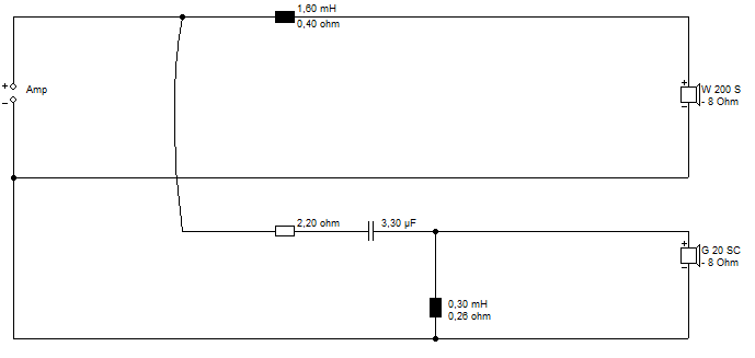
You could design that one by ear, IMO. And you have a circuit already:
The Reveal - Micro Budget Speaker Build

Double component values in the bass filter and it's a series MTM of the same loudness.
Looks like about 4-5L closed box. Tweeter filter maybe could improve. Second order with more resistance?
Dayton Audio - TD20F-4 3/4" Soft Dome Neodymium Tweeter 4 Ohm
You could design that one by ear, IMO. And you have a circuit already:
The Reveal - Micro Budget Speaker Build
Double component values in the bass filter and it's a series MTM of the same loudness.
Looks like about 4-5L closed box. Tweeter filter maybe could improve. Second order with more resistance?
Yeah nick has actually been helping me with my build, but since i had issues with the measurements he has had a hard time teaching me (purely my fault because i couldnt supply him with accurate frd files until now so he spent most of his time going in circles with me). I actually had a pretty descent crossover designed in an almost identical setup as the one you posted above, but it was simulated in xsim using manufacturer measurements, and in the box its quite a lot different and doesnt work to give me a good response. So I decided that for this one and future builds, since i now have the omnimic, that i would rather design my crossovers using actual measured files and save myself some messing about. I just dont understand how to upload series driver frds into two separate single drivers in xsim, or is that what you meant in your post, that i only need to add one woofer parallel to the tweeter and it will give me the right impedance when i tune it with the "woofers in sereis" frd?
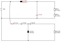
I spent 10 minutes on this, so don't take it too seriously! 😀
Software | Visaton
I just wanted to see what circuit worked best.
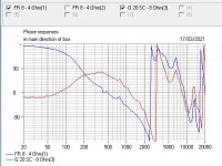
Third order tweeter was the tidiest I could get. Not surprising really with small basses.
I notice Parts Express or Dayton give you the FRD/ZMA files on whatever test baffle they use. Why reinvent the wheel? 🙂
Software | Visaton
I just wanted to see what circuit worked best.
Third order tweeter was the tidiest I could get. Not surprising really with small basses.
I notice Parts Express or Dayton give you the FRD/ZMA files on whatever test baffle they use. Why reinvent the wheel? 🙂
Attachments

Well im trying to learn how to design and build my own speakers so that i can have the freedom to build whatever i want to in the future, and copying or building someone elses design doesnt help me to learn, so thats the main reason for doing it this way, its a learning experience mainly. Im fine with designing the box and port etc, im just unsure now of how to upload my files to xsim. Ive used online frd for those drivers already and in the real world im finding it doesn't work out too well.
So is it right to use the series woofer files as one driver in parallel with the tweeter?
Thanks for your help
So is it right to use the series woofer files as one driver in parallel with the tweeter?
Thanks for your help
Just to double-check, your woofer (LF) measurement is of the two series-wired drivers running together, rather than of each drive unit individually, correct? If so then yes, it's a single summed output you have for the midbass drivers and you would therefore treat them as a single LF unit in Xsim.
For purely theoretical models, as Steve has done above, then you would indeed need to consider the drivers as separate units, because you need to approximate step-loss, diffraction and offsets within the computer modelling software. That does not apply in your case, when you have taken in-box measurements, and the series pair were measured as a single summed output.
For purely theoretical models, as Steve has done above, then you would indeed need to consider the drivers as separate units, because you need to approximate step-loss, diffraction and offsets within the computer modelling software. That does not apply in your case, when you have taken in-box measurements, and the series pair were measured as a single summed output.
Last edited:
Thank you so much for that reply, its been so hard to get someone to explain to me in a way that i understand. And yes the woofers have been measured in series, I was getting confused because the crossovers i have seen on mtm designs had two woofers in series actually showing in xsim. Now that you have explained it i realise they must have been done with theoretical measurements.
So given that i just use one simulated driver for the woofers, i just add one z offset measurement of 0.7, i dont need to double that since it's a summed response?
Also, just for future reference, if i was making a 3 way system with the woofer and sub in series, would i have to add those as separate drivers since the z offset of each one is different?
Re the Z axis, yes, you'll just use the single value which you can derive from your measures, you don't need to double it.
3-way with a woofer and sub wired in series? Assuming the subwoofer and bass driver are different types of units, then you would need to measure them individually on (and off) the design axis, and you would handle them separately in the crossover design, including different acoustic offsets (Z axis). If they are wired in series with each other then that will likely require a series crossover, except in the handful of cases where two different types of bass unit share the same low pass filter -as noted these are few & far between though.
3-way with a woofer and sub wired in series? Assuming the subwoofer and bass driver are different types of units, then you would need to measure them individually on (and off) the design axis, and you would handle them separately in the crossover design, including different acoustic offsets (Z axis). If they are wired in series with each other then that will likely require a series crossover, except in the handful of cases where two different types of bass unit share the same low pass filter -as noted these are few & far between though.
Last edited:
Thank you, that makes things so much clearer for me, ill upload my crossover design later tonight, would you mind giving it a once over for me please before i buy the components? (hopefully i can buy the values i need, or close to).
I plan to make a tv unit with build in 3 way speakers to the left and right and a centre channel in the middle, so the info you just gave me should make that a whole lot easier when i come to design it, i plan to use a tangband w5 sub either side that i hope will be a good fit for that design
I plan to make a tv unit with build in 3 way speakers to the left and right and a centre channel in the middle, so the info you just gave me should make that a whole lot easier when i come to design it, i plan to use a tangband w5 sub either side that i hope will be a good fit for that design
Can someone just take a quick look at my crossover design please and see if there re any issues? I did it using my own measured files and its the best i can do, if i try to cross higher the woofer starts to create an issue due to its unevenness from 3000hz onwards, i want to buy my components but the dip down to 4 ohms on the impedance is making me question whether it will be too low for my av receiver, which can run 6-12ohms, i know its in the high frequencies but id prefer to have an expert tell me its ok before i do something to damage it. I was aiming for 8 ohms


So is my attempt that bad? Lol but yeah no problem, thanks for taking the time , ill just have to get on the laptop to upload them
Can someone tell me please if that above crossover is ok and if the impedance would likely be fine for my receiver?
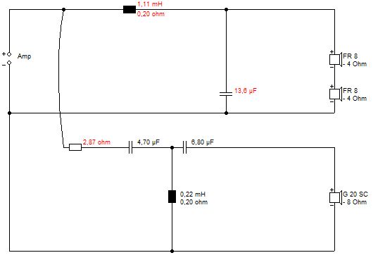
Reason you are struggling on tweeter impedance is that small 0.13mH coil. Something like 0.22mH is more the 6 ohm impedance:
3rd Order / 18 db Butterworth Crossover Table
Bass circuits are less predictable because you need to include bafflestep, but usually the first coil is about 3 times bigger than the second one. I take it this is actually series wired twin bass for 8 ohms overall.
L3 looks overly big to me, and you often bypass it with an 8 ohm resistor to add a bit of bafflestep. Butterworth filters tend to have good impedance. Usually near 1:3 ratio on series components.
Did you try this one?
Thanks for that, ive just tried changing the .13mh coil for a 0.22 and it does raise the impedance, i still end up with tge same 4ohm imp though after 12khz. Also it moves tge crossover point in the wrong direction. Ill input the componants you suggested and see what i get with those
Last edited:
Just tried those values and they dont seem to work with my measured files, im convinced that the two drivers don't mesh well as everything ive tried in the crossover either gives me a good response or a good impedance, never both


I think ive input the components right
I think ive input the components right


- Home
- Loudspeakers
- Multi-Way
- Trying to finish my mtm style speakers