Carlos,
I don't mean in a disrespectful way, building different types of solid/tube/digital amp is like buiding better/different mouse traps, it gets boring/the same/ after a while.
The sound reproduction is not that much different esp. solid state amp.
I don't mean in a disrespectful way, building different types of solid/tube/digital amp is like buiding better/different mouse traps, it gets boring/the same/ after a while.
The sound reproduction is not that much different esp. solid state amp.
You're missing the point. This is a nice fun project you can get working in a couple hours with junk lying around in between all the money pits that take months to complete. Or a really good starter amp for someone who has never built a thing in his life.
Hi Sheldon.... i am happy to see you around
I use to remember you from time to time, as i love to be tuned into Hawai internet radio.... i let it go playing here... i love those musics as i have visited Honolulu down 1981... lovely place.
I still use to listen the songs you have sent me..you are a nice guy.
This amplifier will remember the time we were very young Sheldon, and this is the magic for us, to people that is going to have 50 or 60 years old..... it is easy to recognize the sound characteristic..... lovely sonics for us.
Interesting is that it is flat.... and if you watch specifications obtained from simulator,it is almost so good as modern ones.... very interesting that...also distortion is very small when you stay inside the amplifier limits.... when you go above, it screams alike a pig beeing killed.... distorts as a crazy thing because has not the differential input control...when enters clipping it is terrible!
But... as we do not use to play into clipping levels it sounds delicious....nice, warm and without losses in treble... the bass is awsome dear Sheldon.... and as you have perceived... you can use almost all transistors....have to respect if NPN or PNP... they must be silicon and the output must manage 36 volts and tollerate more than 2 or 3 amperes only.... you can use small transistor almost everywhere... current is small....not more than 5 mA... small transistors can hold that...so...it is something we can build into a saturday using parts from the junk box.... the supply can be wires runned from the Symassym supply, or Roender supply or other 34 volts supply... uses positive and ground only.
Power is enougth..but you can use almost any voltage.... small adjustments may be needed.... so you can have more power if needed or to reduce to use as computer amplifier inside small boxes.
Nice.... it is guaranteed as nice.
Be happy dear sheldon...i hope your nice family is fine too.
regards,
Carlos
Attachments
Dear ttan88..... visit this link uncle charlie is providing you
http://www.youtube.com/watch?v=w3QphsVZm0Q
I agree.... they are almost the same...in special transistor amplifiers.... but within this "almost" there are differences too.
Use a good amplifier..can be your tube amplifiers if you want... also good speakers... play it loud and listen... after that tell me if sounds the same or not.
regards,
Carlos
wg ski..... you've got the point.
congratulations, usually people do not get the point.
Sheldon also got the point..but this do not surprises me...he is someone i already know.
regards,
Carlos
congratulations, usually people do not get the point.
Sheldon also got the point..but this do not surprises me...he is someone i already know.
regards,
Carlos
Re: Dear ttan88..... visit this link uncle charlie is providing you
destroyer X said:
http://www.youtube.com/watch?v=w3QphsVZm0Q
I agree.... they are almost the same...in special transistor amplifiers.... but within this "almost" there are differences too.
Use a good amplifier..can be your tube amplifiers if you want... also good speakers... play it loud and listen... after that tell me if sounds the same or not.
regards,
Carlos [/QUOTe
I agree they do sound different, very small can be detected with a good system and audiophile ears.
today pure audio equipment market is getting smaller and smaller, young people don't use audiophile amplifier anymore. Buying an amplifier whether audiophile or standard are just like any amplifier similar to buying a mouse trap.
BTW I still build amplifiers, just a hobby of mine. This group of enthusiats are very small indeed.
Trust amplifier adjustments
1) Install a 12 to 33 ohms resistance in series with the positive
supply wire.
2) Measuring DC volts at the output, marked "A" into the
schematic, adjust trimpot VR2 till you measure half your supply
voltage.
3) Measuring DC milivolts directly over R7 leads, adjust trimpot
VR12 till you reach 5 milivolts.
4) Repeat steps 2 and 3
5) Check DC voltage over your protective resistance, dividing the
milivolts measures directly over this resistance leads by this
same resistance value.... milivolts must be expressed in
volts...so... 100 milivolts you write 0.1 volt.... you will obtain
something around 25 miliamperes as result of division.
6) Remove your protective resistance, the positive rail one, check
once again the ouput condenser polarity and enjoy your
amplifier.
regards,
Carlos
D.Self Vbe resistor
Hi,
can I suggest a small and easy modification?
Add a resistor position in the horizontal link between the top of R11 and the bottom of R15.
This resistor value can be 0r0 for no effect, or between 12r and 24r for maximal flatness in the Vbe voltage vs current.
I suggest 20r initially for this bootstrapped design with ~5mA flowing through the VAS.
The effect that this resistor gives is to stabilise the Vbe voltage when the DC VAS current changes with mains voltage variation.
Your suggestion was accepted, but as some upgrade
Not to modify schematic or boards because of this modification, even beeing valuable.
This produces a lot of work.... i have to bother Todd Johnson because schematic ...also bother Alex mm because of boards consequences... modify parts list (BOM) and those consequences.
So..the amplifier is ready the way it is..... and folks can use your suggestion if they want..cutting tracks and inserting this resistance under the board or whatever they want.
Modifications, at this point, were all work was made, is a little bit problematic as i have not only this forum to modify all that stuff and produce images and post images..there are other places where i publish that stuff in parallel
But thanks...good cooperation..good idea.... and i accept and agree hundred percent.
regards,
Carlos
Bill of Material.... BOM... or parts list
I am asking Greg Erskine, our Gerskine to include the Trust amplifier into his home pages.... this will be very helpfull for us.
The Dx Amplifier, lower distortion version was not assembled...and when ready to go will be also included.
Here is the parts list:
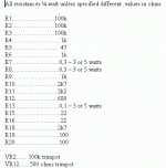
All resistances ¼ watt unless specified different..values in ohms
R1…………………100k
R2…………………100k
R3…………………100k
R4…………………… 1k
R5………………….. 47
R6…………………… 1k
R7....................0,3 – 3 or 5 watts
R8....................0,3 – 3 or 5 watts
R9…………………… 1k
R10…………………2k7
R11…………………2k2
R12.................680
R13...................0,1 – 3 or 5 watts
R15....................22
R16....................22
R18..................2k7
R19..................100
R20..................100
VR2....... 100k trimpot
VR12.......500 ohms trimpot
C1................... ..30pf 35 Volts
C2.................. 220uf 35 Volts
C2a…………… ….100n 35 Volts
C3................. 6800uf 35 Volts...or 8600uf to 4 ohms
C4…………………… 33uf 35 Volts
C5………………… 150uf 35 Volts
C5a.................. 100n 35 Volts
C6................... 100pf 35 Volts
C7....................... 1uf 16 Volts
C8………… …… 220n 35 Volts
C9…………………… 1uf 35 Volts
C10………………… 220n 35 Volts
C11…………………..7,5pf 35 Volts
C12………………….220pf 35 Volts
C13…………………..7,5pf 35 Volts
C14…………………..7,5pf 35 Volts
C18…………………. 1uf 35 Volts
C19……………… 1000uf 35 Volts
C24………………….7,5pf 35 Volts
C16…………………680pf 35 Volts
C17…………………680pf 35 Volts
Q1 …… BC556
Q5...... MJL3281
Q2……… BD139 Q4…… BD139
Q3……… BD139 Q6...... BD140 Q7……….MJL1302
The Trust Amplifier...from the Corporation, is a very fast amplifier alike this bird
But...alike we have into the nature.... there are others faster...piggeons use to beat this bird that cannot catch them in fligth...it is a nice dog figth.... piggeons use to scape.
My dearest nephew, James Mergulhão Green, the one i could find because this forum help, made this picture while visiting his home town that is Rio de Janeiro...this is a local bird we call Gavião (hawk)
An externally hosted image should be here but it was not working when we last tested it.
Listen the Trust amplifier here
your visit will be a honor to me.
I have "insigth" control, so i know the country have visited and person that have visited.
regards,
Carlos
http://www.youtube.com/watch?v=w3QphsVZm0Q
your visit will be a honor to me.
I have "insigth" control, so i know the country have visited and person that have visited.
regards,
Carlos
http://www.youtube.com/watch?v=w3QphsVZm0Q
Here is the hawk image.
I have attached..but something happened..some bug into the image provider.
regards,
Carlos
I have attached..but something happened..some bug into the image provider.
regards,
Carlos
An externally hosted image should be here but it was not working when we last tested it.
All good here Carlos. Glad you enjoy Hawaiian music sometimes. It's like your latest version - simple, direct, pleasing melodies from the heart - no need for deep analysis. I peek in on your threads from time to time, but I can't keep up.
Cheers,
Sheldon
Cheers,
Sheldon
A honor to visit.. cool 😎 music.your visit will be a honor to me.
But , I do hear MY amp playing your music. (lot's of bass -LF)
The fish heard it too, jumping in the tank..😀
Nice simple design..
OS
Attachments
Ahahahah.... yessssss... Bass is nice.
The camera does not capture trebles..so....bass goes dominating the whole thing...there are two ways we have bass increased...when the recording media has losses when register trebles and when we increase them....i have both options!
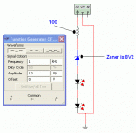
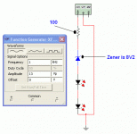
I have made a fast clipping lamp...something to flash when the amplifier reaches the maximum swing undistorted.
No quality to the video.... audio quality was not my worry.... as microphone was in bad position to capture quality..also volume too much loud is saturating the digital camera microphone.
But you can see ligths flashing.
Latter i will post the circuit... a resistance a zener and a Led....simple series thing.
http://www.youtube.com/watch?v=dodhQmsx4qQ
regards,
Carlos
This may be nice to install into speakers
because is driven by the audio..has no supply.... half cicle of audio crosses the zener and ligths the Led.... the speaker out is the connection to this circuit (heheheheh....obvious!)
This one was not calculate correctly.... i have to re-adjust.
But it is nice to see the ligth flashing...in special at nigth.
regards,
Carlos
Attachments
- Status
- Not open for further replies.
- Home
- Amplifiers
- Solid State
- Trust, the most delicious Dx Amplifier


