I've used 5 ohms as the speaker impedance, Troels Gravesen seems have used this value for the original L-pad.
Okay, got it. I wasn't coming up with the original values by using 4 ohms; wasn't sure if I was doing it right.
Evan
A question about resistors. The only place I know to get 2, 5 and 10 watt audio resistors is online. Can I use 1/4 and/or 1/2 watt small carbon film resistors that seem to be available locally?
6L6,
Thanks, and how do I post photos? Is it pretty self-explanatory?
Evan
Yes it is very easy go to advanced, if you're not already in it and click on the paper clip up at the top, next to the smiley face and the text size/font.
I use a remote host site, I've never posted to this site. It's cant be that hard
Please always attach files using DIYaudios hosting. There's nothing more annoying then going to an older thread and seeing that none of the images work because a remote (and now expired) host was used.
Any ideas about the small Radio Shack resistors? I'll be near one in a while and I might stop in if their resistors are suitable for crossovers.
Thanks,
Evan
Thanks,
Evan
You can, just use many in parallel to keep the power rating high enough. I would use metal film rather than carbon comp if those are available.
Well, I went ahead and bought them. I hadn't gotten a response by the time I was near a radio shack. They don't have much under 100 ohms. I bought two 1 ohms because they don't have 1.2 and I was hoping they might me a little off. Amazingly they both measure 1.2 ohms😀. They are 10W wirewound. The 15 ohm I bought are the 1/2 watt carbon type.
The 15 ohm resistors are in parallel, so would they by any chance not need as high a power requirement?
Would they do to test with and then I could order higher power ones if I like the further attenuation?
The 15 ohm resistors are in parallel, so would they by any chance not need as high a power requirement?
Would they do to test with and then I could order higher power ones if I like the further attenuation?
Pascal,
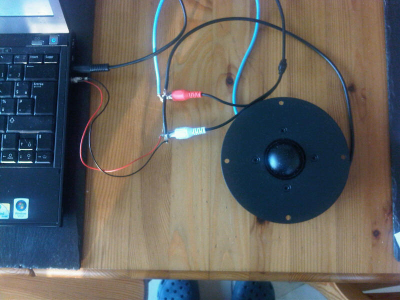
On your impedance measuring jig, is the red and black wires connected to your computer's headphone out? And is the mini plug to rca connected to the microphone in? Also, is each rca lead connected to both the positive and neg lead or is one connected to the positive only and the other to the negative only. It's hard to tell what's connected to what in the pic because all the connections overlay each other.
Thanks
Pascal,
On your impedance measuring jig, is the red and black wires connected to your computer's headphone out? And is the mini plug to rca connected to the microphone in? Also, is each rca lead connected to both the positive and neg lead or is one connected to the positive only and the other to the negative only. It's hard to tell what's connected to what in the pic because all the connections overlay each other.
Thanks
Never mind, I forgot that you posted all that information a while back.
Evan
Hi, I am having trouble using the REW impedance measuring device. I believe I have it hooked up correctly, I have calibrated the system for the resistor, my levels are ok. When I measure I don't get anything at all on the graph. The only tab that displays anything on the graph is the "GD" tab and it is a horn shape starting small at 25hz (start) and gradually expanding towards 20,000hz (end). Any thoughts.
I get an error saying that the input level on the reference input is too low, but if I do the level measurement anyways the levels are OK.
Ok, I have gotten the input level to not give an error message and have gotten the impedance graph to display an image, but I don't believe it's correct. I get a very large peak around 50hz and then it drops pretty sharply back to 4 ohms or so and stays flat all the way to 20k.
Evan
Evan
If you have REW set up, does that mean you have a mic? You can just take a response measurement 1cm from a woofer cone to see fb.
No, I don't have a mic. I build an impedance measuring jig per REW's instructions and was trying to do that measurement.
It seems impossible. None of my measurements look anything like the graphs that I have seen showing impedance and phase. They look more like bad frequency response graphs. My guess is that it is not set up right. Everything that I am reading is too damn complicated, REW's help pages and what people have to say on home-theater-shack assume that you have a postdoc in electrical engineering. I was hoping for some help from Pascal since he was the one that recommended I set this thing up.
I had trouble setting up what I imagine is the same type of jig for LIMP. The problem turned out to be a wiring error where I'd forgotten that a jack was TRS balanced, but that's probably not your problem. It works right when you connect a resistor instead of a speaker? Can you post what you're getting for a speaker?
Hey dumptruck,
I wouldn't doubt that I could be wiring, but I it appears to be right. Not sure what TRS balanced is, but they appear to be standard, shielded cables. There is already a 100 ohm resistor in the jig. Are you saying to attach a resistor between the + and - speaker leads instead of a speaker?
Evan
I'll post a pic I have to remeasure because I haven't saved any.
A balanced TRS jack is something you'd find on pro gear, I'm sure it's not an issue with your soundcard unless it's a pro-ish external type. Make sure your grounds are connected, including the negative speaker terminal, as done by the black wire in this pic of Pascal's hookup:

- Home
- Loudspeakers
- Multi-Way
- Troels NOMEX 164: any thoughts