Roberto,
Why not use a Self EFII Class AB using bipolars?
The harmonic profile of your fet/mosfet Rush cascode has a very good harmonic profile, and it will be preserved in the EFII.
HD
Why not use a Self EFII Class AB using bipolars?
The harmonic profile of your fet/mosfet Rush cascode has a very good harmonic profile, and it will be preserved in the EFII.
HD
Thank you very much for your suggestion AKSA,
your post remembered me I have a IRAUD2000 module I bought years ago: a IRS2092 ( https://www.infineon.com/dgdl/irs2092.pdf?fileId=5546d462533600a401535675f1be2790 ) based amp claiming 350W rms per channel on 8 Ohm that should have been installed to replace the power amp of an instrument amplification, then I didn't use it.
Would you suggest using this preamp to drive the IRS2092 and so lower internal gain accordingly?
Thank you in advance,
Roberto
How did you manage the high input capacity of the mosfet?
Thanks
Roberto,
Why not use a Self EFII Class AB using bipolars?
May I ask you a link to a circuit that can be connected to this "preamp"?
Thanks
Roberto
Hi sulcorebutia,
you can get more “real triode imperfections” and more gain by increasing the R1/R2 ratio.
The bottom p-mosfet needs to take care of the full current, but less than 10Vpp. It can indeed have different characterystics than top n-mosfet.
I’m indeed looking for a low Ciss p-mosfet able to drive a n-mosfet.
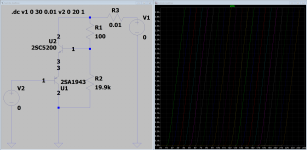
This is another option with strong 2nd harmonic and other harmonics 60 dB below 2nd.
It is inspired by Rod Coleman's shunt cascode and absolutely not optimized.

This is the result with 100 mVp at its input:
It is inspired by Rod Coleman's shunt cascode and absolutely not optimized.
This is the result with 100 mVp at its input:
Code:
Harmonic    Frequency     Fourier     Normalized     Phase      Normalized
 Number       [Hz]       Component     Component    [degree]    Phase [deg]
    1       1.000e+03    3.901e+01    1.000e+00        0.32°        0.00°
    2       2.000e+03    8.399e-01    2.153e-02       90.90°       90.58°
    3       3.000e+03    3.771e-03    9.666e-05        2.80°        2.48°
    4       4.000e+03    5.461e-04    1.400e-05      178.64°      178.32°
    5       5.000e+03    4.423e-04    1.134e-05     -178.76°     -179.08°
    6       6.000e+03    3.678e-04    9.429e-06     -179.04°     -179.36°
    7       7.000e+03    3.152e-04    8.081e-06     -179.23°     -179.55°
    8       8.000e+03    2.759e-04    7.071e-06     -179.34°     -179.66°
    9       9.000e+03    2.452e-04    6.285e-06     -179.40°     -179.73°
Total Harmonic Distortion: 2.153103%(2.153104%)A semplification of the circuit above, with low output impedance and 14 dB of gain with a very predominant 2nd harmonic with negative phase.
The working principle, inspired by Rod Coleman's Shunt Cascode, is the following: V2 is fixed via a filtrered SMPS, V4 is fixed as well through a 7815, so this makes R2 a CCS.
J1 works with local current feedback through R3, that also contributes to its polarization. J1 drain voltage is kept fixed by Q1's emitter, and this increases the bandwidth of the gain stage. The current flowing through R2 must always be higher than the current that will pass through J1, because the output signal is due to the current flowing through R5 multiplied by the resistance of R5, so I(R2)-I(R3) multiplied by R5.
This means that once you have obtained the harmonic slope che you like, you can increase the gain by simply increasing the value of R5 and referring it to a negative voltage instead of ground.

This is the harmonic content at an output of 100 mVp:
This at 1 Vp:
This at 6.55 Vp:
The working principle, inspired by Rod Coleman's Shunt Cascode, is the following: V2 is fixed via a filtrered SMPS, V4 is fixed as well through a 7815, so this makes R2 a CCS.
J1 works with local current feedback through R3, that also contributes to its polarization. J1 drain voltage is kept fixed by Q1's emitter, and this increases the bandwidth of the gain stage. The current flowing through R2 must always be higher than the current that will pass through J1, because the output signal is due to the current flowing through R5 multiplied by the resistance of R5, so I(R2)-I(R3) multiplied by R5.
This means that once you have obtained the harmonic slope che you like, you can increase the gain by simply increasing the value of R5 and referring it to a negative voltage instead of ground.
This is the harmonic content at an output of 100 mVp:
Code:
Harmonic    Frequency     Fourier     Normalized     Phase      Normalized
 Number       [Hz]       Component     Component    [degree]    Phase [deg]
    1       1.000e+03    1.001e-01    1.000e+00      180.00°        0.00°
    2       2.000e+03    5.949e-05    5.946e-04       90.02°      -89.98°
    3       3.000e+03    8.881e-08    8.876e-07      172.13°       -7.87°
    4       4.000e+03    1.822e-08    1.821e-07       14.93°     -165.06°
    5       5.000e+03    8.304e-09    8.300e-08      -94.44°     -274.44°
    6       6.000e+03    1.912e-08    1.911e-07       91.50°      -88.50°
    7       7.000e+03    3.308e-08    3.306e-07     -170.97°     -350.97°
    8       8.000e+03    1.115e-08    1.114e-07      164.33°      -15.67°
    9       9.000e+03    3.315e-08    3.313e-07     -155.18°     -335.18°
Total Harmonic Distortion: 0.059459%(0.059453%)
This at 1 Vp:
Code:
Harmonic    Frequency     Fourier     Normalized     Phase      Normalized
 Number       [Hz]       Component     Component    [degree]    Phase [deg]
    1       1.000e+03    1.000e+00    1.000e+00      180.00°        0.00°
    2       2.000e+03    5.956e-03    5.955e-03       90.00°      -89.99°
    3       3.000e+03    1.115e-04    1.115e-04     -179.99°     -359.99°
    4       4.000e+03    1.669e-06    1.669e-06      -90.51°     -270.51°
    5       5.000e+03    6.133e-08    6.131e-08       -2.20°     -182.20°
    6       6.000e+03    1.746e-08    1.746e-08     -142.80°     -322.80°
    7       7.000e+03    1.668e-09    1.668e-09      -37.96°     -217.96°
    8       8.000e+03    5.760e-09    5.759e-09      114.23°      -65.77°
    9       9.000e+03    1.534e-08    1.534e-08      148.40°      -31.59°
Total Harmonic Distortion: 0.595602%(0.595601%)
This at 6.55 Vp:
Code:
Harmonic    Frequency     Fourier     Normalized     Phase      Normalized
 Number       [Hz]       Component     Component    [degree]    Phase [deg]
    1       1.000e+03    6.556e+00    1.000e+00      180.00°        0.00°
    2       2.000e+03    2.733e-01    4.168e-02       90.00°      -90.00°
    3       3.000e+03    4.193e-02    6.396e-03     -179.98°     -359.98°
    4       4.000e+03    5.645e-04    8.610e-05      -90.36°     -270.36°
    5       5.000e+03    3.166e-03    4.830e-04        0.07°     -179.93°
    6       6.000e+03    1.335e-03    2.036e-04      -89.90°     -269.90°
    7       7.000e+03    9.215e-04    1.406e-04     -179.89°     -359.89°
    8       8.000e+03    5.624e-04    8.579e-05       90.13°      -89.87°
    9       9.000e+03    3.621e-04    5.523e-05        0.14°     -179.86°
Total Harmonic Distortion: 4.217639%(4.217641%)
Attachments
- Home
- Amplifiers
- Solid State
- Triode-like curves from a n-channel DMOS (and not only)