Hi,
I would like to ask your comments on a design I've implemented on SS starting from George (Tubelab) UNSET (see details on dedicated section of the forum).
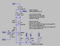
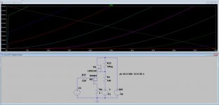
Driving a N-channel Depletion-mode DMOS (I've used the LND150 because they work well with high voltages, available where I want to implement this circuit) from the cathode through a pmosfet and giving local feedback through a voltage divider from drain to gate to ground.
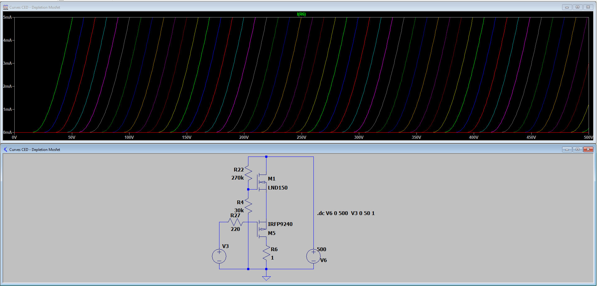
Curves are very promising, and of course the local feedback (and so the reference gate voltage of the pmosfet) can be modified accordingly to change the curves of the two mosfets.
Of course the same concept can be applied to other SS devices too.
Thanks in advance for your feedback,
Kind Regards
I would like to ask your comments on a design I've implemented on SS starting from George (Tubelab) UNSET (see details on dedicated section of the forum).
Driving a N-channel Depletion-mode DMOS (I've used the LND150 because they work well with high voltages, available where I want to implement this circuit) from the cathode through a pmosfet and giving local feedback through a voltage divider from drain to gate to ground.
Curves are very promising, and of course the local feedback (and so the reference gate voltage of the pmosfet) can be modified accordingly to change the curves of the two mosfets.
Of course the same concept can be applied to other SS devices too.
Thanks in advance for your feedback,
Kind Regards
Attachments
You're only studying voltage treshold bands in depletion mosfets.
Attachments
Last edited:
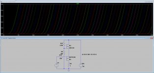
Not sure where dreamth is coming from, but there is no actual "design" shown, just the test jig to generate the local feedback curves in ltspice. Where would the output be taken from, what is the load, and why do you use a 150W rated part to drive a 0.74W rated part? 😉
Hi tikiroo,
the pmosfet comes directly from the circuit I use to test the same UNSET feedback on output pentodes. I haven’t adapted to the specific DMOS, also because it can be used with more powerful mosfets too.
The two mosfets have to be considered as a single device, input at gate of pmosfet, load on top o of depletion.
UNSET schematic can be found attached here: UNSET Beta Board Build
This was my take of an SE amp using pentodes only: Single Ended: the pentode retaliation
Here I've substitued the pentode with the mosfet.
This was my take of an SE amp using pentodes only: Single Ended: the pentode retaliation
Here I've substitued the pentode with the mosfet.
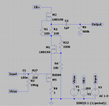
This is the schematic of a possible application as a preamp with 2Vrms at input and 60Vrms at output: a CCS loaded gain stage.

This is the simulation I've got, absolutely not optimized.
What I will try to put together is a single stage SS power amp, class A in SE: more current and way less gain, so more local feedback applied to the upper device compared to the schematic above.
This is the simulation I've got, absolutely not optimized.
Code:
Harmonic Frequency Fourier Normalized Phase Normalized
Number [Hz] Component Component [degree] Phase [deg]
1 1.000e+03 8.488e+01 1.000e+00 0.09° 0.00°
2 2.000e+03 1.209e-02 1.424e-04 89.25° 89.16°
3 3.000e+03 5.595e-04 6.592e-06 19.19° 19.10°
4 4.000e+03 2.118e-04 2.495e-06 142.84° 142.75°
5 5.000e+03 1.162e-04 1.369e-06 -166.19° -166.28°
6 6.000e+03 5.473e-05 6.448e-07 -170.36° -170.45°
7 7.000e+03 5.211e-05 6.139e-07 179.11° 179.02°
8 8.000e+03 4.552e-05 5.363e-07 -178.95° -179.04°
9 9.000e+03 4.055e-05 4.777e-07 179.16° 179.07°
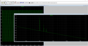
Total Harmonic Distortion: 0.014260%(0.014236%)What I will try to put together is a single stage SS power amp, class A in SE: more current and way less gain, so more local feedback applied to the upper device compared to the schematic above.
Attachments
Last edited:
This is the result changing the local feedback voltage divider to 2M2 - 39k, always with 2Vrms at its input and now an output of 110Vrms with a THD of 0.015577%:
Code:
Harmonic	Frequency	 Fourier 	Normalized	 Phase  	Normalized
 Number 	  [Hz]   	Component	 Component	[degree]	Phase [deg]
    1   	1.000e+03	1.544e+02	1.000e+00	    0.09°	    0.00°
    2   	2.000e+03	2.403e-02	1.556e-04	   89.36°	   89.27°
    3   	3.000e+03	1.085e-03	7.028e-06	   17.99°	   17.90°
    4   	4.000e+03	3.850e-04	2.493e-06	  143.15°	  143.06°
    5   	5.000e+03	2.118e-04	1.371e-06	 -166.45°	 -166.54°
    6   	6.000e+03	1.003e-04	6.495e-07	 -170.27°	 -170.36°
    7   	7.000e+03	9.481e-05	6.139e-07	  178.39°	  178.30°
    8   	8.000e+03	8.365e-05	5.416e-07	 -179.69°	 -179.78°
    9   	9.000e+03	7.412e-05	4.799e-07	  178.77°	  178.68°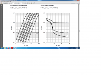
Total Harmonic Distortion: 0.015577%(0.015555%)I can see it working well as a voltage amplifier, although there is still no actual load on the circuit in post#6. The LND150 has very low input capacitance. As a single stage power amplifier (choke or transformer loaded?) I wonder how well the resistor feedback will drive the high gate capacitance of a decent sized mosfet, this is the big difference to deal with compared to a pentode.
Then you would need to see if there is any advantage compared to just driving the gate (will be low impedance due to local feedback) via a source follower.
Then you would need to see if there is any advantage compared to just driving the gate (will be low impedance due to local feedback) via a source follower.
Thanks for your feedback tikiroo,
the local feedback voltage divider can be scaled based on the voltage and current capability (and input capacity) of the n-mosfet: with 60V and a device able to deliver 15A, the divider can be 330-33 Ohm.
The advantage of the p-mosfet on bottom is that the p-mosfet shares part of the power in class A (proportional to the feedback ratio), so the system (p-mosfet plus n-mosfet) can run at higher currents with the same voltage supply.
yes you are right, its output Fourier components are surprisingly similar to a linear triode, at least inside simulation.This is the schematic of a possible application as a preamp with 2Vrms at input and 60Vrms at output: a CCS loaded gain stage.
This is the simulation I've got, absolutely not optimized.
Code:Harmonic Frequency Fourier Normalized Phase Normalized Number [Hz] Component Component [degree] Phase [deg] 1 1.000e+03 8.488e+01 1.000e+00 0.09° 0.00° 2 2.000e+03 1.209e-02 1.424e-04 89.25° 89.16° 3 3.000e+03 5.595e-04 6.592e-06 19.19° 19.10° 4 4.000e+03 2.118e-04 2.495e-06 142.84° 142.75° 5 5.000e+03 1.162e-04 1.369e-06 -166.19° -166.28° 6 6.000e+03 5.473e-05 6.448e-07 -170.36° -170.45° 7 7.000e+03 5.211e-05 6.139e-07 179.11° 179.02° 8 8.000e+03 4.552e-05 5.363e-07 -178.95° -179.04° 9 9.000e+03 4.055e-05 4.777e-07 179.16° 179.07° Total Harmonic Distortion: 0.014260%(0.014236%)
What I will try to put together is a single stage SS power amp, class A in SE: more current and way less gain, so more local feedback applied to the upper device compared to the schematic above.
Attachments
Thank you sulcorebutia,
it is like "Shade's" local current feedback, but here in voltage.
The first advantage is that the input impedance is very high and with a very low capacitance, so it is very easy to drive it.
The second one is that by changing the voltage divider ratio you can "select" the triode characteristics.
R22 can be connected to the left side of C2.
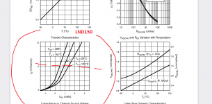
LND150 seems a good candidate for preamp, LND250 could be for higher current ones, but others should work as well.
Do you think I should dig Nelson Pass' threads to find components able to make it not only a preamp stage but also a single stage power amp? Anyone has some suggestions?
it is like "Shade's" local current feedback, but here in voltage.
The first advantage is that the input impedance is very high and with a very low capacitance, so it is very easy to drive it.
The second one is that by changing the voltage divider ratio you can "select" the triode characteristics.
R22 can be connected to the left side of C2.
LND150 seems a good candidate for preamp, LND250 could be for higher current ones, but others should work as well.
Do you think I should dig Nelson Pass' threads to find components able to make it not only a preamp stage but also a single stage power amp? Anyone has some suggestions?
Thank you sulcorebutia,
it is like "Shade's" local current feedback, but here in voltage.
The first advantage is that the input impedance is very high and with a very low capacitance, so it is very easy to drive it.
The second one is that by changing the voltage divider ratio you can "select" the triode characteristics.
R22 can be connected to the left side of C2.
LND150 seems a good candidate for preamp, LND250 could be for higher current ones, but others should work as well.
Do you think I should dig Nelson Pass' threads to find components able to make it not only a preamp stage but also a single stage power amp? Anyone has some suggestions?
Hi Zintolo, there is not much information from google of "Cascading a N-channel Depletion-mode DMOS with a P-Channel enhancement mode mosfet". So, could it be a novel idea?😕 Well, perhaps we can name it as Zintolo Cascode 😀
Can you tell us more how to bias the top depletion dmos in making the cascode to work in low voltage(<60V)? In my opinion, Pentode with Schade feedback can handle high voltage easily. Zintolo Cascode's potential seems to be in the lower voltage area.
For Nelson Pass's amp, if you can make a pair of Zintolo Cascode to replace the front differential IRF9610 amp, I think you can already make a big difference.
I've done some research too and I've never found something similar (except for tube similarities I've cited before).
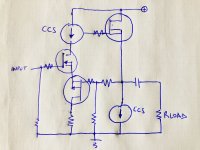
Again during my morning shower I think I've found how to make it a single ended amp, keeping the same configuration but inspired by SpreadSpectrum's Corona amp (Corona: An Ultra-Low Distortion A2 DHT SE Amp Prototype ):

So the nfet is driven directly to its gate, and loaded by a CCS to have a very high gain. DC coupled to this there's a CCS loaded source follower (of course there can be more in parallel), and its output gives feedback directly to the pfet on bottom of the nfet driver.
It becomes a single gain stage amp with local feedback.
Being the gain of the driver very very high (a CCS loaded nfet), the amount of feedback is very high as well, guaranteeing very low THD.
Again during my morning shower I think I've found how to make it a single ended amp, keeping the same configuration but inspired by SpreadSpectrum's Corona amp (Corona: An Ultra-Low Distortion A2 DHT SE Amp Prototype ):
So the nfet is driven directly to its gate, and loaded by a CCS to have a very high gain. DC coupled to this there's a CCS loaded source follower (of course there can be more in parallel), and its output gives feedback directly to the pfet on bottom of the nfet driver.
It becomes a single gain stage amp with local feedback.
Being the gain of the driver very very high (a CCS loaded nfet), the amount of feedback is very high as well, guaranteeing very low THD.
Attachments

One version I built.
This circuit is called a "bastode" and it is a diff pair but with dissimilar devices.
I explored this idea back in 2016 and it works great, with a very triode like sound character.
I used the bastode circuit to experiment with positive current feedback, but it sounds great without it.
There is a lot of information about the bastode circuit on tubecad.
Thanks Circlomanen!
I'm happy to hear from you that the first configuration has already been built by you 5 years ago and it is sounding very well. I wasn't aware of the bastode configuration.
Is the configuration at post #13 already been used before?
Thank you in advance
I'm happy to hear from you that the first configuration has already been built by you 5 years ago and it is sounding very well. I wasn't aware of the bastode configuration.
Is the configuration at post #13 already been used before?
Thank you in advance

Here is a much less complex version.
The resistor loaded version has a lot of distortion and does sound a bit "warm" and "thick". The distortion values gets much improved with a constant current source or "MU" modulated current source.
Is the configuration at post #13 already been used before?
I don´t know. I have tried to use the gate of the N device for signal input, but I prefer to use the ground level gate of the P device.
Thanks again Circlomanen!
Also the DF drops to around 0.5 when resistor loaded, I would say.
A CCS plus a resistor could define the warmness and thickness of the stage.
What is the final wattage you've obtained?
PS
I'll read your thread: Positive Current Feedback simple Zen amp
Also the DF drops to around 0.5 when resistor loaded, I would say.
A CCS plus a resistor could define the warmness and thickness of the stage.
What is the final wattage you've obtained?
PS
I'll read your thread: Positive Current Feedback simple Zen amp
What is the issue you noticed in the low voltage range? The first circuit swings almost rail to rail. To bias differently whilst keeping a specific feedback ratio, add a resistor bypassed by a capacitor on the bottom of the feedback voltage divider: you keep the same ratio in ac and you can change the dc reference of n-mosfet gate.Can you tell us more how to bias the top depletion dmos in making the cascode to work in low voltage(<60V)?
@sulcorebutia
I think I've understood what you said: by simulating the very first circuit with low voltage supplies (below 100V), triode curves stops around 50V. To solve that, just give a positive DC reference to the feedback voltage divider instead of grounding the bottom resistor and you'll move all curves on the left.
I think I've understood what you said: by simulating the very first circuit with low voltage supplies (below 100V), triode curves stops around 50V. To solve that, just give a positive DC reference to the feedback voltage divider instead of grounding the bottom resistor and you'll move all curves on the left.
- Home
- Amplifiers
- Solid State
- Triode-like curves from a n-channel DMOS (and not only)