Hi all
Hoping to get some help with this tricky problem.
I'm trying to repair a Wharfedale powercube SPC 12. The fault is that it just doesn't power up.
I can't seem to find a service manual or schematic.
The fault appears to be with a circuit intended to shut the PSU down if there is any DC detected at the amplifier outputs.
On the amplifier board there is a high pass filter and 3 transistors which it appears should pull the "dc_ps" line low if any DC I present on the output.
Between this line and the +15v line on the PSU PCB there's an optocoupler, on the other (mains) side of the optocoupler seems to be where the issue lies.
Even though the optocoupler isn't on (I have even tried lifting it to see if it was leaking) the circuitry (a set of smd transistors, diodes, and zeners which are proving difficult to trace out) seems to be pulling what measures as a 5v5 zener diode - it's surface mount and lacks any markings - low which in turn pulls the vcc line low on the power supply driver IC. The driver (ir2153d) needs enough current to pull it's internal zener all the way to 15v5 to operate.
If I lift this 5v5 zener, the PSU and amplifier seem to work just fine. There's no DC on the output, just a small 500kHz signal as expected for a D class amp. Rails measure ok too.
I guess I'm hoping someone has had experience repairing this problem or can at least point me to a schematic/service manual. My searching has turned up nothing. I'm not sure how forthcoming Wharfedale are with service manuals so I haven't gone that route yet.
Happy to provide any details / probing as needed. If I need to I could trace that circuit out but it will be tricky it's a 2 sided PCB and the layout is a bit all over the place.
The diodes and transistors all seem to test ok, at least using diode mode on my meter (in circuit) but the fault must be here somewhere surely...
Thanks in advance!
Sorry, I haven't got a circuit diagram or a service manual.
If nobody else has, can't you draw up this rather simple DC detecting circuit (though on a double-sided PCB)? You say there is "a high-pass filter and three transistors". Normally you use a (very) low pass filter to detect DC.
If nobody else has, can't you draw up this rather simple DC detecting circuit (though on a double-sided PCB)? You say there is "a high-pass filter and three transistors". Normally you use a (very) low pass filter to detect DC.
I will try to trace it out when I get a block of time. And measure some voltages. Hopefully the fault will reveal itself that way.
I figured it out! The shutdown circuit has 2 separate activation paths - by DC on output (which turns on the opto isolator) OR if input voltage is above a threshold.
There's a voltage divider on B+ and it turns out the high side 0603 resistor R21 was not 390k but more like 350k (and lower in use according to the measured voltage) which was triggering the overvoltage prematurely.
Line voltage here is on the high side (250v) so the combination was enough to cause a problem. The voltage at the divider can only be around 16v before Q5 turns on, and it was 17.6v, ZD2 is around 15v
Q5 or the opto turning on turns on Q4 which in turn turns on Q6 which pulls the oscillator C pin to gnd. The drop in VCC seems to be a side effect, although it doesn't matter as pulling the other pin to gnd shuts down the oscillator anyway.
I couldn't measure the resistor directly in (dead) circuit due to the main caps being essentially across it, or I'd have spotted this before.
This also explains the reported symptom of "works occasionally" if the line voltage was low enough and that resistor was behaving, it would probably start up and pull the rail down enough to prevent re-activation.
Now I just need a replacement resistor as I don't have any in stock.
Excuse the chicken scratches, I'll draw a better diagram tomorrow. So much trouble for such a little resistor [emoji28] but a good learning experience.
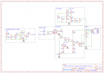
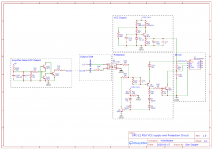
Much better diagram - hope this helps someone down the track.
EasyEDA link:
Wharfedale SPC12 Power supply -
EasyEDA
EasyEDA link:
Wharfedale SPC12 Power supply -
EasyEDA
Attachments
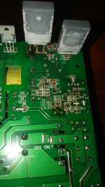
A successful repair/mod. Replaced R21, originally 0603, with a through hole part. I calculated it would be dissipating 0.25w and it would need to drop over 300VDC under normal operation. Seemed like a lot to ask of a tiny SMD resistor. I found a spare through hole to the + rail and soldered the other end down to the original pad, added a drop of cyanoacrylate for reinforcement. Kapton tape and heatshrink should keep it safe from any shorts.
 . Good craftsmanship.
An 0603 resistor is not rated for 340V or anthing like that, it should be 1206 at the very least.
2010 would be a wiser choice.
That R21 resistor failed for a reason - its far too small, a mistake in the engineering of the circuit I'm afraid.
2010 would be a wiser choice.
That R21 resistor failed for a reason - its far too small, a mistake in the engineering of the circuit I'm afraid.

Thanks Mark, that's the only conclusion I could draw as well.
Perhaps someone scaled down a working design for layout purposes, without much thought for the component ratings.
Here is a table for some typical thick film smd resistors, they rate 0603 at 25v and isolation of 50v. It appears they do not rate any for more than 200v, even in the larger footprints.
Perhaps someone scaled down a working design for layout purposes, without much thought for the component ratings.
Here is a table for some typical thick film smd resistors, they rate 0603 at 25v and isolation of 50v. It appears they do not rate any for more than 200v, even in the larger footprints.
My mistake, 50v (by 0603 I mean the 1/16 size here)
Confusing having two similar standards for the component sizes [emoji43]
Confusing having two similar standards for the component sizes [emoji43]
Well, this bloody thing came back for another visit, dead again. I thought, damn, must have screwed up my repair.
But thankfully, my repair was still good, no signs of deterioration.
Instead, one of R20/R41 had gone open, causing a VCC supply of only 8v or so instead of the required 15.6v. Very difficult to measure in circuit, so with no power applied, I supplied 18v where the resistors should have been (current limited to 5mA) ... and saw 15.6v at VCC. Removed the resistors and indeed one was open. No real visible signs either.
Replaced both with 220k 2W resistors since I didn't have 180k on hand, and it lives once again, pending full reassembly and testing. Note these should be up to the job, between the two they will be dissipating less than 1W.
What's the voltage rating of the 220k's you subbed in?
Maybe a couple 47k's in series would be better, voltage-wise 😉
Just a thought -- in case you haven't already put it back in service . .
Cheers
Maybe a couple 47k's in series would be better, voltage-wise 😉
Just a thought -- in case you haven't already put it back in service . .
Cheers
They are big beasties, not sure the rating but I've used them in tube amps without a hitch [emoji106] I will bench test it a while before sending it home
My friend Wharfedale SPC12 having no power issue. I fing out that the output only +24V -24V instead of +70V -70V.
Thanks to you ubergeeknz, I managed to fixed it by replace R21 with my spare 1/4w 390K ohm resistor. The R20 and R41 still OK after de-solder and measure.
Thanks to you ubergeeknz, I managed to fixed it by replace R21 with my spare 1/4w 390K ohm resistor. The R20 and R41 still OK after de-solder and measure.
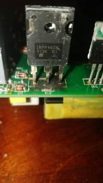
@kinnupa1 looks like at least the mosfets are gone, possibly the driver IC is damaged as a result, and I would check the transformer in case that's the root cause.
That IR2153 shows up as a HIGH/LOW driver for FETS. If it blows up in this way its likely because of cross-conduction in the output stage.
I'd go for a replacement part for the original mosfet with less gate charge, and mod the dead time on the 2153 for slightly increased dead time.
Also replace all the electrolytics around that high/low driver, my bet is on some external capacitor going high impedance
I'd go for a replacement part for the original mosfet with less gate charge, and mod the dead time on the 2153 for slightly increased dead time.
Also replace all the electrolytics around that high/low driver, my bet is on some external capacitor going high impedance
IMHO, I can't see the need to specify different parts, I would replace with equivalents and leave it at that. The IR2153 should be reasonably foolproof. Yes, replacing the electrolytics won't hurt, if you're in there it's worth doing along with the 1/4w overvoltage resistor.
- Home
- Amplifiers
- Power Supplies
- Tricky SMPS fault in Wharfedale SPC 12