Most of the losses in SMPS are switching losses as opposed to conduction losses like one would be led to beleive. There are some drop-in Silicon carbide 247 package fets that could do the same job with less turn-off time. Hence by replacing them you could repair it so it never fails again.
C3M0280090D is a part i want to test for a couple of things.
C3M0280090D is a part i want to test for a couple of things.
Thank you for finding the culprit. I found out that removing the orange/rusty residue in the area of R21 with a cotton swab soaked in contact cleaner (you can see the stuff on the picture in post #8) have fixed it for me, unless I dont use the subwoofer for several days. Then I have to pull the plug for a moment, and then it is back again. So maybe this lighter approach will fix it for someone who's subwoofer isn't quite dead. I believe its worth a try at least, before going to the soldering solution.
@EggsBegs the replacement isn't too challenging and ought to solve the issue permanently. But that's good to know. Possibly scrubbing the carbon tracking away would have fixed it for a time in my case, but I did not trust it to be a reliable repair.
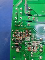
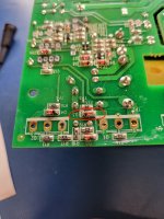
I have a fault with what appears to be the SMPS on a Wharfedale SPC 12 similar to post #17. The IR2153 has blown, both mosfets (IRFP460A) Q1 and Q2 test bad. Also C14, C18, and C10 electrolytics have high ESR/open and/or capacitance out of spec. I have already ordered replacement parts for the mosfets and capacitors. I decided to test the diodes and found that D3 (appears to be connected to gate of mosfet Q1) and zener ZD1 (near the IR2153 that had blown) are shorted (confirmed out of circuit). I also confirmed out of circuit that NPN Q3 (also near the IR2153) has its base-emitter shorted (65R).
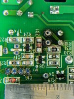
I don't have experience with SMD rework. From what I found online, the diodes appear to be SOD-80 packages (see attached). NPN Q3 has the markings as 2F or ZF (not exactly sure). I have attached images of the three components. One image I have included a ruler to provide a scale (in that one ZD1 was already removed).
I am hoping someone could help me identify suitable replacement SMD parts / Digikey part#'s for Q3, D3, and ZD1?
After some googling I am thinking Q3 would be a SOT-23 2N5551S / MMBT5551. Would this be the correct replacement for Q3? :
https://alltransistors.com/transistor.php?transistor=53474
https://alltransistors.com/adv/pdfdatasheet_kec/2n5551s.pdf
(I have also asked this question on the EEVBlog and that post is pending a response. I am also posting here as it appears some member's have experience with this unit as they have created a schematic of part of the SMPS).
https://www.eevblog.com/forum/begin...hen-mounting-high-voltage-mosfet-on-heatsink/
Attachments
Following up on my last post, I did some searching on Digikey/Mouser. Would the following parts be suitable replacements as follows? :
Q3: https://www.mouser.ca/ProductDetail/onsemi/MMBT5551LT1G?qs=HVbQlW5zcXXlUyy8htIqAQ==
D3: https://www.digikey.ca/en/products/detail/central-semiconductor-corp/CLL2003-TR-PBFREE/5325131
ZD1: https://www.digikey.ca/en/products/...nductor-diodes-division/TZM5247B-GS08/4874715
Q3: https://www.mouser.ca/ProductDetail/onsemi/MMBT5551LT1G?qs=HVbQlW5zcXXlUyy8htIqAQ==
D3: https://www.digikey.ca/en/products/detail/central-semiconductor-corp/CLL2003-TR-PBFREE/5325131
ZD1: https://www.digikey.ca/en/products/...nductor-diodes-division/TZM5247B-GS08/4874715
I went over my suggested replacements for Q3, D3, and ZD1 with someone locally and it looks like the parts I have chosen for D3 and Q3 would be overkill. ZD1 that was selected should be ok. I will continue with these selected parts.
I will update with the results of the attempted fix.
I will update with the results of the attempted fix.
After replacing the above parts I mentioned in post #24/#25 I measured the output voltage (expecting to see +15/-15V) however there was no voltage present. The voltage on pin 1 of the IR2153 is measuring 11.08V.
On the schematic that was posted earlier, VDC for the VCC Supply was stated at 340V. For me, I am measuring 320.8V.
I am wondering if the same situation that the OP had with R21 is also applicable here. Perhaps I should try lifting ZD4 (5v5 zener) and see if it powers on (similar to the OPs experience -- if I am understanding their post correctly.)
With the IR2153 removed voltage where pin 1 would be was measured at about 16V.
Tried lifting ZD4, Q5, and R21 (measured 362.1K out of circuit). Also lifted pins 5 through 8 on the IR2153. Pin 1 on the IR2153 still low at around 11.5V. Connected the IR2153 such that only pins 1 and 4 were connected. Voltage at pin 1 still measuring low at 13.5V.
At this point I have given up on the repair.
Diodes D3 and D4 show both 32 ohms to both directions. Should I remove them to measure properly?I have also low VDC volts about 305. What could be the cause for that?
How much voltage there should be after R20/R41 and before R24? I have now 9.5V and I think it's not enough.
Yes, 9,5V is not enough. The '2153 will probably stay off, since it will only see about 8,9V even if Q3 is saturated. I haven't looked up the '2153 under-voltage threshold, but its likely to be higher than that -- at least within part-to-part tolerances. You want the Zener that sets Q3's Base voltage to be conducting current -- that's its job.
I don't see D3 or D4 in the earlier schematic fragment posts. But if your meter is displaying the same DC resistance both directions, that could be a problem. Does it not have a 'Diode Range'?
Cheers
I don't see D3 or D4 in the earlier schematic fragment posts. But if your meter is displaying the same DC resistance both directions, that could be a problem. Does it not have a 'Diode Range'?
Cheers
It does have diode range and it shows 33 "something", perhaps ohms, both ways and also resistance measure shows 33.
By the way, voltages at rectifier KBJ2510 are AC 227v and DC 315v. I wonder, where it raises to 340v?
By the way, voltages at rectifier KBJ2510 are AC 227v and DC 315v. I wonder, where it raises to 340v?
33 'anything' both directions, especially considering that it's the same on both ranges, is a definite problem.
All I have for a schematic are the bits others have posted, and there wasn't a KBJ2510 that I could find. Both voltages might be low, depending on which leads you're measuring. But if you have AC and DC that high between any two leads on a rectifier, that's another problem. Any chance you're measuring between a secondary Ground and an un-isolated primary?
All I have for a schematic are the bits others have posted, and there wasn't a KBJ2510 that I could find. Both voltages might be low, depending on which leads you're measuring. But if you have AC and DC that high between any two leads on a rectifier, that's another problem. Any chance you're measuring between a secondary Ground and an un-isolated primary?
I measured from the rectifier itself. Outer pins are dc and inner ac. Ac (227) is same as from the wall. I understood that in that kind of rectifier dc volts are 1.4 x ac and that's what it is now.
That'll need to be investigated. I'm gonna cave and lookup what the '2153 requires, but I'll be really surprised if the part is willing to do its job on that voltage.
But the KC Chiefs are on at the moment, so it'll take me a bit to get to it.
But the KC Chiefs are on at the moment, so it'll take me a bit to get to it.
Yes, unless I'm completely misreading page 4 of the '2153 data sheet, this part will sit quietly, doing nothing at a pin 1 voltage of 8,8V.

There is still a small chance that a turn-on surge would meet the threshold, then would function briefly before the lower threshold was violated. But it would not be reliable. (Operation would vary with line variations, and load demands, and probably other things I haven't thought of.) Isn't this the thread where other posts described a badly stretched 390k quiescent supply resistor. If so, use 2 or 3 or more in series to replace it -- a single part doesn't have a high-enough voltage rating.
Cheers
Last edited:
- Home
- Amplifiers
- Power Supplies
- Tricky SMPS fault in Wharfedale SPC 12