More possible additions for later:
Switchable linear - logarithmic scale.
Adjustable lower current limit.
Switchable linear - logarithmic scale.
Adjustable lower current limit.
That was not the initial aim, and difficult to achieve. So the IC is measured in four ranges: 10m / 100m / 1 / 10, the last two require further development obviously.I don't quite see how the hardware design in post #37 achieves a logarithmic sweep of collector current across the X axis (Ic from 1uA to 10mA) using a [linear] sawtooth as the stimulus.
The design is only erupted this week.
Mark is sharp, no problem. In my country, this directness is normal. I did not even notice....you complain about...
Yes, they do exist. In the scientific world they're used... and expensive.Did you hear about logarithmic amplifiers?
I've never done a design with them, types, models, products. I know a diode is used to produce the logarithmic curve, but that's an (inverse) exponential (e^x) actually, and results in deviations from the ideal log (10^x) scale.
Input is welcome!
Also, I tried to have this design as generic as possible, and is 'freeware' without any rights or other legal matters.
So everybody is welcome to grab it and develop and use it as one likes.
Improvements and other contributions can be posted here, to benefit all.
I will post the cad file tomorrow - it's drawn in orcad92 (i'm used to).

I think this design is not capable of accepting very good (if at all) a log sweep input, either log triangle, ascending or descending sawtooth.I don't quite see how the hardware design in post #37 achieves a logarithmic sweep of collector current across the X axis (Ic from 1uA to 10mA) using a [linear] sawtooth as the stimulus.
During the extremes (lower beta's), the correction signal will be high but with less accuracy because of lack of signal at low values of Ic, or steep rising peaks at high values of Ic.
As "dxf" is not accepted as an upload extension, remove the ".dxo" part from the fileneme to keep the .dxf extension.
I tried to import the dxf in another cad application, but not very succesfull...
Attachments
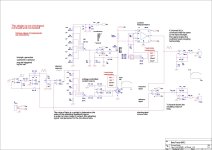
Irecognise the controlles current source an the INA, but the drawing looks a bit twisted... V3 is the saw/tri input.
Some details are lost in upload.
And most simu's won't capture the trick either: it's a timed circuit, and simu's cannot do XY plotting. That was out of the imagining bounderies from the start of the digital era onwards. I've met lot of smart sw-programmers last 30+ years, but no one ever got that temporarely view, let alone the realisation. Sampling, Shannon, Showing. That's all.
The output of X3 [LN] should be the inverse beta trace as mentioned above.
I ran the pdf through Illu for a proper jpg - fanfare for the common man.
Attachments
What is needed is a four decade sweep generator (at least) - the circuit would compensate I guess/hope to extract the requested MarkJ log beta curve... Anyone?Analog devices has ICs for that.
Yes, I used static voltage instead of the sawtooth. INA works, 10mA translates into 5V. CCS also works.
But: U3A, + input is sawtooth or my static voltage, - input must be exactly the same otherwise output goes to rail voltage.
But: U3A, + input is sawtooth or my static voltage, - input must be exactly the same otherwise output goes to rail voltage.
I tried the analog divider, it works so far.
hfe by simulation is 271.
hfe calculated by circuit is 254 = 2,54V.
The error comes from INA103 input current 2,6uA.
FET INA111 should be ok, no input current, but the model is bad, not works.
10 / 0,039452 = 254
2,6uA removed: 10 / (0,039452 - 0,0026) = 271
I checked BC550 with higher beta and BD139 with lower beta and it is ok.
Last edited:
Actually, one could percieve U3A as the input stage of an audio amplifier.otherwise output goes to rail voltage
On the (+) input is the reference (input) signal, on the (-) input is the 'amplifier's' output, so the output of U3A is the correction/adjusting/feedback signal.
If the rest of the circuit is not optimised, its output can go beserk very soon.
Start small.
Nice to see the concept proven!Added FET buffers, pretty accurate now.
I understand your intentions but... You also could percieve U3A and U3D as open loop which is very hard to handle.Actually, one could percieve U3A as the input stage of an audio amplifier.
On the (+) input is the reference (input) signal, on the (-) input is the 'amplifier's' output, so the output of U3A is the correction/adjusting/feedback signal.
If you want to look at U3A as a follower, it expects: -input equal to +input. In this case output will be equal to +input. If -input is to small, U3A raises output until -input is equal to +input.
If there was a valid feedback loop, which is not the case.
Because if U3D voltage go up on -input, output will go down. But then, Ic will go down and measured voltage too. So while -input of U3A should go up for equilibrium, it goes down. So, it can not work.
U3D must be an adder. U3A as compound amp with all that circuitry in the loop is at least questionable.
Still, where is hfe ? Buffer output is the original sawtooth plus (or minus!) a correction voltage.
Further, the starting conditions are totally undefined.
Imho U3A should be another INA.
Then, the base current should be generated purely by the correction signal.
To start with...
open loop:
.
Last edited:
Got your point and indeed, two open loop opamp in series.
U3A and U3D should be combined into one opamp!
And furthermore, TRX is an inverter... for voltages on its load at the collector. But there's an INA measuring the current, so no inversion there!
Back to the drawing board. Post in due time.
U3A and U3D should be combined into one opamp!
And furthermore, TRX is an inverter... for voltages on its load at the collector. But there's an INA measuring the current, so no inversion there!
Back to the drawing board. Post in due time.

Now the regulation of Ic works, constant IC with different transistors, if preadjusted.
I tried the same today but simulation with AD and BB opamp fails... LM324 works.
Still, the beta output gives no plausible result. Tried some adjustments.
See the LED readout for actual beta.

I tried the same today but simulation with AD and BB opamp fails... LM324 works.
Still, the beta output gives no plausible result. Tried some adjustments.
See the LED readout for actual beta.
- Home
- Design & Build
- Equipment & Tools
- Transistor HFE - IC curve tracer?