How about multiple Vce traces ?
1V , 2V ... 7V for example.
Otherwise I would just make Vce variable with a pot, so the change in trace shape can be observed comfortably.
1V , 2V ... 7V for example.
Otherwise I would just make Vce variable with a pot, so the change in trace shape can be observed comfortably.


It might be amusing or frightening to plot the output current of "VG1" in post #164. That current might be uncomfortably large at the end of the swing, where the driven load is only (0.1R + (7 * diode_slope_dv_di))
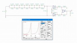
A possibly simpler, and extremely accurate method of generating an exponential is to use a negative resistor:

Of course, you are not going to find a -47K resistor in Mouser's inventory, but they can be synthesized quite easily. I have probably given some examples on this forum, but the Master, Stephen Woodward has published many examples in EDN and/or Electronic Design
Of course, you are not going to find a -47K resistor in Mouser's inventory, but they can be synthesized quite easily. I have probably given some examples on this forum, but the Master, Stephen Woodward has published many examples in EDN and/or Electronic Design
You're right, but gladly it's a simu only.It might be amusing or frightening to plot the output current of "VG1" in post #164. That current might be uncomfortably large at the end of the swing, where the driven load is only (0.1R + (7 * diode_slope_dv_di))
Now we can multiply all resistor values (R11 - R17) with 100 to reduce the current.
... I notice I haven't update the annotation of the measure resistor (also R15), but it depends on various factors if this one has to change too.
And, by changing the waveform of VG1, I forgot to adjust the dc offset level from 1.4Vdc (4 diodes) to 2.5Vdc (7 diodes).
Being familiar with Aimspice, and consequently being extreme accurate, Tina as with a graphical interface makes me somewhat lazy.
Post #164 was from my new job laptop ("You need a reliable laptop, here, take this." "Is it expensive?" "Four digit's." {continental}), so an update follows this weekend. (This post is done with an very old osx10.10.5, the keys are not that much reliable anymore: typo's possible! - Also, that Aimspice is running on W2k in vmware on that mbookpro.)
It would be very much appreciated if you can dig up some references, as this is a very nice (and maybe more simple) approach and alternative to build a solid 'expo-gen'....but the Master, Stephen Woodward has published many examples in EDN and/or Electronic Design.
As I said, S. Woodward made abundant use of the concept; references might not be instantly accessible directly, but if you are persistent enough, you will find them. Example here:It would be very much appreciated if you can dig up some references, as this is a very nice (and maybe more simple) approach and alternative to build a solid 'expo-gen'.
https://www.edn.com/dpga-conditions-signals-with-negative-time-constant/
However, a small picture (or sim) is worth a thousand words:
Attachments
Seems to contradict with the pictures in #116, or what reasons are implied?Ic over several decades combined with beta range of transistors is problematic for several reasons.
If M1 is the discharge switch, I wonder if a exp-gen could be made with a 555!However, a small picture (or sim) is worth a thousand words...
What Ic in mA span are you thinking of ?Seems to contradict with the pictures in #116, or what reasons are implied?
The first picture (#116) implies a span of three decades, and Mark points to 4.5 decades in #16, which is an ultimate span.What Ic in mA span are you thinking of?
Add:
In mA's I'd say, from 0.01mA up to 1000mA, which is 5 decades, to cover nearly all bjt's, exept the brutal ones.
In mA's I'd say, from 0.01mA up to 1000mA, which is 5 decades, to cover nearly all bjt's, exept the brutal ones.
You want a dynamic range of 1:100.000 on a log x scale. Beta variation added is 1:50. Combined 1:50.000.000... The divider has an input / output range of 10V, opamps a bit higher.Add:
In mA's I'd say, from 0.01mA up to 1000mA, which is 5 decades, to cover nearly all bjt's, exept the brutal ones.
So you are dealing with voltages down to nV for any functional unit of the circuit. Noise, inaccuracy, saturation, clipping.
You need autoranging of Rsense and Rina during the Ic sweep. Small new challenge. 🙂
What kind of transistor do you want to test over 5 decades of Ic ?
From my point of view it does not make any sense.
Some small signal transistors only have a max. Ic of less than 10 mA.
A power transistor used in an output stage only needs to be tested around working current.
My plan is:
0.2 mA to 2mA for low current input stages.
1 mA to 10 mA for hot input stages.
5 mA to 50 mA for VAS transistors.
25 mA to 250 mA for driver transistors
125 mA to 1250 mA for output devices
Locky-Z curve tracer goes up to 1000 mA and down to sub-100uA. I haven't done a lot of work with it at super low currents so I don't have observations and experience about the level at which measured current values become untrustworthy. The unit includes range switching relays that make audible clicks during sweep operations.
See...The unit includes range switching relays that make audible clicks during sweep operations.
- Home
- Design & Build
- Equipment & Tools
- Transistor HFE - IC curve tracer?