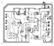
All done.... Speaker ground return, Boucherot Cell, R13 and R12 now return to PSU ground at the top of the board.
I have more copper clad board arriving tomorrow, so time to fire up the laser printer and the laminator 🙂
I'll let you know how I get on.
I have more copper clad board arriving tomorrow, so time to fire up the laser printer and the laminator 🙂
I'll let you know how I get on.
😎 that's a really neat board layout.
(There is one more 'refinement' that could be done although it would make minimal difference at the power levels involved here, and that is to take the NFB (negative feedback point) from the actual speaker output point (before the coupling cap of course).
Its the same problem... resistance of the print affecting things. The right hand end of R4 is the feedback take-off point and so only that one point is a correct 'copy' of the audio signal. Ideally the right hand end of R4 should be returned to the trace connecting to the pos end of the 2200uF.
Because of the low powers here it will make little difference but if you build more powerful designs then its something to consider.
Great work though
Thanks 🙂
If it will make no difference at these power levels, then I'll not bother, as I'd have to redesign as the trace connecting the Zobel's resistor to the collector of Q6. I could route that around the top of C8, through the middle of the speaker output pads, and that would leave me a path, but if there'd be no appreciable advantage, I'll call it done, but thanks for the heads up re: resistance.
I've designed a better PSU for it using a LM338 instead of a LM317... just for headroom and then I can have a much smaller sink on the regulator.
Just waiting for stuff to arrive now.
it is models:
.model ss9012 pnp is=2.0417e-14 bf=143.3 vaf=47.75 ikf=0.5743 ise=75.86f ne=2 br=14.345 nr=0.999 var=86.14 ikr=0.4265 isc=1.585f nc=1.0087 rb=57.5 irb=7.943u rbm=8.09 re=0.02 rc=0.743 cje=35.1p vje=0.866 mje=0.411 cjc=19.1p vjc=0.787 mjc=0.394 xcjc=0.349 xtb=1.413 eg=1.0885 xti=3 fc=0.5 Vceo=20 Icrating=0.5 mfg=Fairchild
.model ss9013 npn is=3.40675e-14 bf=166 vaf=67 ikf=1.164 ise=12.37f ne=2 br=15.17 var=40.84 ikr=0.261352 isc=1.905f nc=1.066 rb=63.2 irb=5.62u rbm=22.1 re=0.02 rc=0.7426 cje=3.53e-11 vje=0.808 mje=0.372 cjc=1.74e-11 vjc=0.614 mjc=0.388 xcjc=0.349 xtb=1.4025 eg=1.0999 xti=3 fc=0.5 Vceo=20 Icrating=0.5 mfg=Fairchild
.model ss9014 npn is=2.87599e-14 bf=377.5 vaf=123 ikf=1.1841 ise=4.7863f ne=1.5 br=4.79 var=11.29 ikr=0.275423 isc=1.44544e-14 nc=1.5 rb=200 irb=1e-5 rbm=10 re=0.56 rc=5 cje=1.7205e-11 vje=0.6905907 mje=0.3193434 tf=5.89463e-10 cjc=6.2956p vjc=0.4164212 mjc=0.2559546 xcjc=0.451391 xtb=1.8881 eg=1.2415 xti=3 fc=0.5 Vceo=45 Icrating=0.1 mfg=Fairchild
.model ss9015 pnp is=28.76f bf=125.5 nf=1 vaf=123 ikf=0.6041 ise=4.79f ne=1.5 br=4.79 nr=1 var=11.29 ikr=0.275423 isc=14.454f nc=1.5 rb=200 irb=10u rbm=10 re=0.56 rc=5 tf=837.7p cjc=20.96p vjc=0.5164 mjc=0.656 xcjc=0.451 Vceo=45 Icrating=0.1 mfg=Fairchild
The 2SC2240 is a lot lower dissipation which may or may not be a factor in your intended use. The 2SC2611 is a different package but electrically should be OK.
As ever it depends on the exact use these are put to as to whether they would be wholly suitable. For audio they probably would be fine.
Sorry for another interruption. The 2SC2611 isn't working with this amp but the 2SC2240 does and it's playing music already. I am just concerned about the much lower dissipation of the 2SC2240. Is the dissipation critical factor in an amp?
Thanks again.
If the 2SC2611 doesn't work then I would first of all check that the device is genuine and also that the pinouts are as expected and of course that it is fitted correctly.
There are so many problem and fake devices around that you have to be very sure 🙂
The dissipation is determined by the circuit rather than the transistor and so the only way to determine that is by measurements of current through the device and voltage across it. From that you can calculate the power dissipated. Also bear in mind the dissipation can vary with an AC signal as the voltage across the transistor rises and falls with the current doing the same.
So the transistor you fit will not change the dissipation seen, it is up to you to ensure it is always within the datasheet limits.
The 2sc2611 pinouts are as per the data sheet and was placed correctly onto the board but somehow, it just does not start the amp. As soon as I replaced them with the 2sc2240, the amp came to life. I am not sure if they are fakes but it was brought from my trusted local shop.
How do I determine the dissipation? Measurement across B and C or C to E?
How do I determine the dissipation? Measurement across B and C or C to E?
You need the voltage across C and E and also the current flowing in either the emitter or the collector (which can often be deduced from measuring voltage across any resistor in series with C or E). Multiply the two and you have the dissipation under static conditions.
For example in Pook's circuit we might have 15 volts across the TIP41 output transistor and 25 millivolts across the 0.5 ohm.
25mV means a current of 0.025/0.5 is flowing. That calculates to 50 milliamps.
That gives a dissipation in the TIP41 of approximately 0.75 watts (750mW)
For example in Pook's circuit we might have 15 volts across the TIP41 output transistor and 25 millivolts across the 0.5 ohm.
25mV means a current of 0.025/0.5 is flowing. That calculates to 50 milliamps.
That gives a dissipation in the TIP41 of approximately 0.75 watts (750mW)
My measurements are as follow:
1) TR03 (2SC2240) : across C and E = 33.03V
R23 (33.5 ohm) = 160.5mV (in series with E of TR03)
therefore : 0.1605/33.5 = 0.004791 = 4.791 mV
: 4.791 x 33.03 = 158.2 mV
2) TR04 (2SC2240) : across C and E = 32.85V
R24 (33.5 ohm) = 160.3mV (in series with E of TR04)
therefore : 0.1603/33.5 = 0.004785 = 4.785 mV
: 4.785 x 32.85 = 157.1 mV
The 2SC2240 has a power of dissipation of 300 mV. Which means I am within the specs under static condition. Do I need to measure them while the amp is playing?
Last edited:
You would only be able to measure (calculate) the currents dynamically by using a scope to see the change in voltage across the transistor and the resistor, but it sounds as though you will be OK with this as the static dissipation is so low.
While we're thanking Mooly, I'd just like to add mine too.
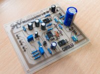
Built and tested the amp today. Works flawlessly, and sounds really, really nice! It sounds really warm in the mid range.. very retro... a whiff of the valve about it. So much so I've named it appropriately 🙂 Bass is really quite tight and transient.
Nice little amp!
The finals are on a separate heatsink (not included in shot). Seems a shame to hide it away in a box LOL
Save
Save
Save
Attachments
Last edited:
You're very welcome guys, and yes, that is a great looking board, one of the nicest I've seen actually. Those trusty old Veropins always come in handy 😀
Hi
Only just saw this thread. A couple of questions -
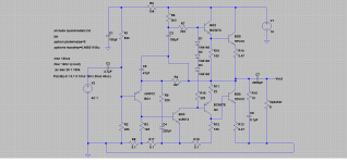
- why not use fully complementary outputs? If you are using TIP41, use TIP42 as well rather than 2x TIP41's.
- still using Miller capacitor to compensate? It's been shown since Bailey's 1968 circuit that you can use phase lead compensation instead. Simulations show that there is a tenfold reduction in intermodulation distortion (in this case 1kHz mainly) under the test conditions I tried (19kHz+20kHz at 40mV peak input each).
Only just saw this thread. A couple of questions -
- why not use fully complementary outputs? If you are using TIP41, use TIP42 as well rather than 2x TIP41's.
- still using Miller capacitor to compensate? It's been shown since Bailey's 1968 circuit that you can use phase lead compensation instead. Simulations show that there is a tenfold reduction in intermodulation distortion (in this case 1kHz mainly) under the test conditions I tried (19kHz+20kHz at 40mV peak input each).
That's a really neat looking board, pook. Do you plan to sell it?
I hadn't planned on doing, no. No one will ever see it again once it's inside the speaker enclosure... but every time I look at the speaker, I'll know what's inside it... so I gave it my best work. I just can't do half-assed.. it seems morally wrong LOL
You're very welcome guys, and yes, that is a great looking board, one of the nicest I've seen actually. Those trusty old Veropins always come in handy 😀
Yup.. gotta love veropins 🙂 I was going to have edge mounted sockets for all the cabling, but I thought I;d use these.. put in the wrong way, so I can solder wires directly to the underside and hide all the cabling neatly.
Just remaking the PSU using a LM338 now, as the LM317 version was getting a little warm when I was testing the amp this morning.
Time to do some carpentry! 🙂
Save
Time to do some carpentry! 🙂
Not something I am very good at tbh.
John... designs like this are almost infinitely tweakable but I would definitely say that using a Quasi output stage like this is one of the reasons for the designs excellent subjective sound quality.
You make a good point on the compensation cap and this is a change that is easily implemented to try it out.
Attachments

Bear in mind, the use this amp will be put to... namely communications reception, short wave broadcasts and casual FM radio reception.
It's probably complete overkill for the intended use, but I've learned a great deal making this, which is my first audio amp build.
Any alterations to the design will almost certainly be academic only 🙂
I'm enjoying the discussion however... Just reading up about the Miller theorem now.
Too much information.... too little time!
- Status
- Not open for further replies.
- Home
- Design & Build
- Parts
- Transistor help (2SC9012)