Well done  and amps like this have the potential to sound really good.
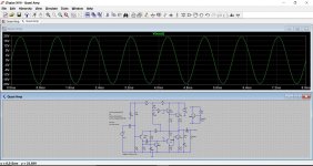
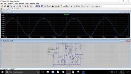
Remember that LT shows the 'peak' voltage on the trace and not an RMS quantity. The fixed bias of the amp is a limitation and could impact on sound quality. Ideally you should have at least 20ma or so flowing in the outputs which you can easily check by measuring the DC voltage across the 0.47 ohm and calculating using ohms law. So you should see around 4.7 millivolts across those with no signal.
and amps like this have the potential to sound really good.Remember that LT shows the 'peak' voltage on the trace and not an RMS quantity. The fixed bias of the amp is a limitation and could impact on sound quality. Ideally you should have at least 20ma or so flowing in the outputs which you can easily check by measuring the DC voltage across the 0.47 ohm and calculating using ohms law. So you should see around 4.7 millivolts across those with no signal.
Rebuilt it with the BD139/140s What a difference!! Much more grunt. Still draws very little power too. Averaging around 800mA.. the odd peak at 1A.. but pretty transient.
21mA flowing in the outputs on idle.. double checked with voltage, which show at 4.9mV.
Everything is cool... doubt the finals even need the heatsinks I have for them.
I have no scope, so can't be certain of how it's set up, but I have a good ear for audio, and I think it sounds lovely!
Thanks again for all your help.
I can't help but think though... is there any reason I can't increase the source voltage to this amp? Everything in it is pretty over-specified for the 15v supply.
That's great 🙂
Yes, you can increase the supply but beware that the quiescent current may well increase. Remember I mentioned early on about the bias network being a limiting factor.
Ideally you should replace that network with a transistor and preset to enable you to adjust the current accurately. It is easy to do.
Like this. The transistor can be 'any' type but should be in thermal contact (and electrically insulated from) the heatsink. A BD139 would be ideal.
The preset would be a 2k2 type and you MUST begin with it set to MAX resistance so that it appears as a 2k2 between base and emitter. That gives the lowest bias current.
Also notice the change in bias resistor network to allow for the mid point voltage to be accurately set. The values depend on the supply chosen and assume R2 in this diagram was a 100k preset.
This shows a 45 volt supply. Remember that things start to get hot a lot more quickly on a higher supply. Keep the bias as low as possible consistent with good sound. Once you get over a couple of milliamps you will find all audible distortion disappears.
Attachments
I'll have a play with that this afternoon while it's still on breadboard.
I've learned a lot throughout the course of this thread. Thanks very much.
I've learned a lot throughout the course of this thread. Thanks very much.
..I'm assuming that if it's not on the same heatsink, then bias voltage will drop as the temp rises?
So far.... no heatsink necessary, but that's only up to 25v. Even at 25v, all transistors seem to be at ambient temp.
So far.... no heatsink necessary, but that's only up to 25v. Even at 25v, all transistors seem to be at ambient temp.
An amp like this definitely needs a heatsink. Its only the low supply voltage and low current that is saving the day at the moment as you only have a around 150 milliwatts dissipation per device on 15 volts. Assuming the current is not much higher on 25 volts then you are probably still looking at only around 400 milliwatts. Play the amp loud and they will get hot, and if you then measure the bias current it will probably be quite a bit higher.
Not having the bias transistor not on the heatsink would cause the bias voltage to drop (but very quickly and only by a small amount) as the transistor stabilised in temperature. The temperature rise of the outputs would far outpace it and thermal runaway could occur... or at the very least the bias would be very variable.
Not having the bias transistor not on the heatsink would cause the bias voltage to drop (but very quickly and only by a small amount) as the transistor stabilised in temperature. The temperature rise of the outputs would far outpace it and thermal runaway could occur... or at the very least the bias would be very variable.
It's perfectly well behaved as it is at 24 volts... gets a little warm when playing loud with a 28x50mm sink on each final. More than loud enough for what I need it for.. I may even drop it to 20V.. still plenty. I think I'll call this one done so I can crack on with the rest of the project. I'll start making a board.
I've enjoyed this... my first audio project 🙂
I've enjoyed this... my first audio project 🙂
I've enjoyed this... my first audio project 🙂
That is what it is all about
Good luck with the board... these type of circuits usually transfer over well.
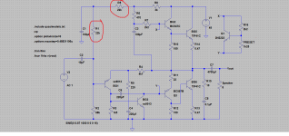
I see you are doing your own thing at the input (mixer) 🙂 Mixing signals is a topic on its own, what you have will work but its not ideal because of interaction between the inputs. Ideally an opamp configured as a 'virtual earth' stage should be used to eliminate that issue.
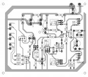
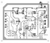
The board... your speaker ground return will cause the current flowing in that trace to modulate the (distort) the inputs because there will be a potential difference between all the input grounds.
I would break that trace and loop the speaker and zobel connection back to the main power supply input ground at the top.
BD140 for the input device ? Yes it will work but a small signal high gain device is better.
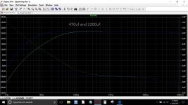
The 470uF speaker coupling cap is placing a limit on the bass response. 2200uF would be a more typical value.
I'll do a simulation of the response.
The board... your speaker ground return will cause the current flowing in that trace to modulate the (distort) the inputs because there will be a potential difference between all the input grounds.
I would break that trace and loop the speaker and zobel connection back to the main power supply input ground at the top.
BD140 for the input device ? Yes it will work but a small signal high gain device is better.
The 470uF speaker coupling cap is placing a limit on the bass response. 2200uF would be a more typical value.
I'll do a simulation of the response.
Attachments
The thing about learning, is getting an answer leads to more questions than you had in the first place! LOL. You're probably getting sick of me by now... but I am seriously grateful.
I thought that series resistor and cap was a Boucherot Cell? I suppose it was just called that in what I've been reading.
Re: input/output intermodulation... Ok.. I can split that track, but if I then loop it back up the top to the main PSU input negative terminal, won't it still be connected to the input grounds... just by a different path, or should the input grounds be floating somehow? Sorry if this seems like a stupid question. A quick sketch on my board design would help me contextualise what you mean maybe... if you have the time.
Re: Q1.... I'll see what else I have lying around.... I presume something like a 2N5089 would be better? If so... I'll see if I have one. I have a bunch of BC560s.. would they be suitable? I've also got a few BC327-40. Also a couple of BC556ABU devices. I'm just trying to avoid driving to CPC again (it's only 14 miles away and the temptation to drive there rather than wait for postage is great) 🙂 If I have to though... I'd rather get something ideal, rather than a compromise.
Thanks for the sim showing the bass roll off... that is quite pronounced below 100Hz. I should have known that! I'm only a beginner, but I was reading about that the other day. Rookie mistake, and trying to retain too much information too quickly.
I know the input network is not ideal, but it will be rare that inputs will be used simultaneously. This active speaker's main use will be used with a communication equipment most of the time, and only one device at once most of the time. I wanted it to sound nice because listening to broadcast stations and FM radio stations with communication gear's in-built speakers is tragic! If this was going to be used in a more hi-fi oriented context, I'd not be doing it.
Thanks again for your patience with a beginner.
Save
Save
Save
You're right 😉 it is more correctly a Boucherot Cell. Zobel network is a name I've grown up with and clung to over many years. Old habits die hard and all that.
All it does is terminate the amplifier at HF, in other words present a load to the amplifier that helps prevent instability. Amplifiers of your type are usually super stable and can often operate correctly without this and the often included output inductor.
The grounds and grounding in general is a complicated subject. On your design the original layout would modulate the audio signal simply because each point along that ground track would be at a different voltage when driving a load.
Move the speaker return and that doesn't happen. You also have to remember how the amp works and how the action of feedback tries to keep the output voltage an exact replica of the input.
So returning the speaker ground to the main 0V input point of the PCB means that although the wire from there back to the power supply will vary in voltage, the input ground and the negative feedback return point will not because there is no significant current flowing in that trace.
A BC556 should be ideal I would have thought.
Have a read at this from post #14:
3 stage LIN topology - NFB tappings?
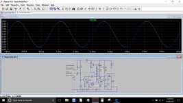
Look at your circuit below. I have added some resistances to the ground track at the bottom. This kind of follows your original layout with everything tapping off this trace.
Look at the difference as the load is changed from 8 ohm to no load. In the last diagram we return the output transistor and the load back to the power supply reference point. Now the distortion has 'vanished' because there are no high currents flowing in the ground connection.
Look at the difference as the load is changed from 8 ohm to no load. In the last diagram we return the output transistor and the load back to the power supply reference point. Now the distortion has 'vanished' because there are no high currents flowing in the ground connection.
Attachments

- Status
- Not open for further replies.
- Home
- Design & Build
- Parts
- Transistor help (2SC9012)