That BU406 BF parameter looks way too high. I used to use these transistors in line output stages and the current gain was very low
I wouldn't like to say how accurate all these models are. Here is a BU508
All these line output transistors have pretty dismal forward gain in reality, at least in the terms we think of for audio.
That said the simulation is fine with the 508 as well.
Code:
.model BU508 NPN(Is=148.5p Xti=3 Eg=1.11 Vaf=100 Bf=30 Ise=1.355n Ne=1.413 Ikf=8.245 Nk=.8069 Xtb=1.75 Br=2.131 Isc=529.1p Nc=1.567 Ikr=1.689 Rc=32.64m Cjc=303.6p Mjc=.3333 Vjc=.5 Fc=.5 Cje=910.8p Mje=.3333 Vje=.5 Tr=16.1u Tf=22.02n Itf=183.6 Xtf=18.91K Vtf=10 Vceo=1500 Icrating=8 mfg=TFK)All these line output transistors have pretty dismal forward gain in reality, at least in the terms we think of for audio.
That said the simulation is fine with the 508 as well.
2SC1951 replacement
Sorry for the interrupting. I need some help to figure if I can replace the 2SC1951 with the 2SC2240 or the 2SC2611. Please see the attached document. I have these 2SC2240 and 2SC2611 with me. Thank you and sorry again for interrupting your tread.
Sorry for the interrupting. I need some help to figure if I can replace the 2SC1951 with the 2SC2240 or the 2SC2611. Please see the attached document. I have these 2SC2240 and 2SC2611 with me. Thank you and sorry again for interrupting your tread.
Attachments
The 2SC2240 is a lot lower dissipation which may or may not be a factor in your intended use. The 2SC2611 is a different package but electrically should be OK.
As ever it depends on the exact use these are put to as to whether they would be wholly suitable. For audio they probably would be fine.
As ever it depends on the exact use these are put to as to whether they would be wholly suitable. For audio they probably would be fine.
Thanks Mooly. It's for an old sansui integrated amplifier. I intend to use the 2SC2611 but am not sure if the twice as high voltage is suitable. Is the lower dissipation of 2SC2240 suitable for use in an amplifier?
Last edited:
The higher voltage is fine as it just means the device can withstand that across collector and emitter before breaking down.
You're welcome 🙂
And when you power this (assuming its a normal power supply and not an SMPS) then use a 'bulb tester' in series with the mains. It can save a lot disappointment as it helps protect the output transistors from overload in the event of a construction error.
Also start with low bias which means having one and maybe two of those series diodes shorted out to begin with.
Got my internet back.... Yay!!!
Ok.. thanks again for running those sims.
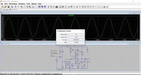
I'm not sure I'm using LTSpice correctly, but I'm getting the final output power at just over 4 watts.
Does this seem right to you?
Save
The maximum power output depends on the supply voltage. A 15 volt supply can never deliver more than around 3 watts into 8 ohms.
(15/2)/√2 is 5.3 volts rms.
Watts = V squared/R so for 8 ohms that is 3.5 watts RMS. Knock a bit off for loses in the output stage and you are looking at around 3 watts RMS.
(15/2)/√2 is 5.3 volts rms.
Watts = V squared/R so for 8 ohms that is 3.5 watts RMS. Knock a bit off for loses in the output stage and you are looking at around 3 watts RMS.
The maximum power output depends on the supply voltage. A 15 volt supply can never deliver more than around 3 watts into 8 ohms.
(15/2)/√2 is 5.3 volts rms.
Watts = V squared/R so for 8 ohms that is 3.5 watts RMS. Knock a bit off for loses in the output stage and you are looking at around 3 watts RMS.
Yeah.. that's what I was thinking... I was expecting less than 4.
Cheers.
Will build in breadboard later this week and report back 🙂
Lets see what the simulation shows. This is right at the onset of clipping and we have 4.36 Vrms available across the 8 ohm load.
That works out to 2.36 Wrms. Guess I was over optimistic with the loses and wasn't accounting for the relatively high emitter resistors.
The good news is that you wouldn't really be able to tell a 2 watt amp from a 4 watt.
Really 🙂
Have a read at this:
A Test. How much Voltage (power) do your speakers need?
Attachments
Will build in breadboard later this week and report back 🙂
Good luck and remember...... use a current limited (bulb limiter) supply to avoid problems when first powering up.
Just a quick question:
Wouldn't a fast blow fuse serve as well as a lamp for current limiting?
I don't have a suitable lamp.
Wouldn't a fast blow fuse serve as well as a lamp for current limiting?
I don't have a suitable lamp.
The lamp is generally better because of the way it works (its non linear resistance as current increases). A fast blow fuse is better than nothing though.
A lot also depends on the power supply you are using. If its a switch mode type then a bulb on the primary side is out of the question.
A lot also depends on the power supply you are using. If its a switch mode type then a bulb on the primary side is out of the question.
All you need then is a 60 or 100 watt (or even a 40 watt) filament bulb from something like an old table lamp. Filament bulbs are still available in various guises at Poundland and Home Bargains. Just wire it in series with the mains feeding the transformer.
I'll see what I can find in Home Bargains later. Or... venture into the cupboard under the sink.... where only the brave would venture! Somewhere in there... hidden behind old, probably banned substances, there may be some 40W candle type lamps from back in the day. I certai8nly haven't cleaned that cupboard out since around 2003 LOL.
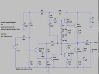
No specific reason, in LTspice for generic circuits like this you will find the models make little difference. I didn't mean to pick different, just me being to quick and not keeping it consistent.
I would really suggest you go with something like the BD131/BD132 for the drivers though.
Look at the totally random models (and in reality unsuitable ones) that I picked here. Does it work... yes.
(Transistors in LTspice never fail or burn a hole in your screen when overloaded 😉)
I would really suggest you go with something like the BD131/BD132 for the drivers though.
Look at the totally random models (and in reality unsuitable ones) that I picked here. Does it work... yes.
(Transistors in LTspice never fail or burn a hole in your screen when overloaded 😉)
Attachments
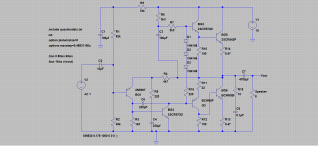
Well.. I built it. Sounds nice.
Not as powerful as I thought it would be though. I'm getting just under 3v at the speaker. The LTSpice sim suggested 6. The finals remain stone cold even at full chat... PSU cold... It's only a 1.5A PSU.
I'm using BC557/547s though.. not BD131/132s. CPC had none... discontinued apparently.
Oh well... it works 🙂
- Status
- Not open for further replies.
- Home
- Design & Build
- Parts
- Transistor help (2SC9012)