
question is when i replace two resistors that are needed. should i connect both 2n3055 at once or one by one t osee how it works ?
Great result so far - and 55v at the power supply cap sounds good.also small transistors are not warm at all so thats good i think btw if i reduce input volume jsut right sound is small but clear
Connect both. Make sure you solder the correct wire to the correct pins. Third wire goes to the metal L-profiles.question is when i replace two resistors that are needed. should i connect both 2n3055 at once or one by one t osee how it works ?
Again test first with a bulb. If all is well, you should have enough power for a small party.
After that you can leave out the bulb circuit.
Last edited:
sadly i have to wait for resistors to arrive i dont have a replacement rn 😀 i cant wait to try it out xdd
btw i wonder what is the real purpose for those resistors ? transistors cant work without them ? how it works, i only know that wone is connected to one of the transistors
My guess has always been that these are emitter resistors. Its' very difficult to see from the pictures.
Anyway, they are there for a reason. They only way to know if they are bad is to desolder the coil around them and to measure their resistance.
Anyway, they are there for a reason. They only way to know if they are bad is to desolder the coil around them and to measure their resistance.
If they are indeed emitter resistors, they are there to stabilize the idle current through the output transistors. If you would bypass them, you would have to reset the idle current, and you would have the risk of thermal runaway and destruction of the output transistors. So, better be patient 😉
Take them out, they have to go anyway.
Maybe one of them is still good so it could be measured.
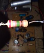
You could try to find out the colour code. I would think that one of them is not too badly burned.
Maybe one of them is still good so it could be measured.
You could try to find out the colour code. I would think that one of them is not too badly burned.
i will try it but if my theory is that resistors burned and only wire was left so it was glowing like bulb xdddTake them out, they have to go anyway.
Maybe one of them is still good so it could be measured.
You could try to find out the colour code. I would think that one of them is not too badly burned.
btw for ones that are interested xdd here are what are those resistors. one on right was 2.7M Ohms 1% second one is too burned to read the colors. wires dont measure anything, resistors measure like sometimes 300k sometimes 600 or more i am not sure why
Is that the colour code? That would be Red - Violet - Green / Tolerance 1% = Brown.one on right was 2.7M Ohms 1%
- Home
- Amplifiers
- Solid State
- transistor amp not working after shorting output