i am more scared of tube amps now xdd i had one before, its really scarry. but now i have one for practicing its like new tech so its not scarry at all. but this solid state i am not sure 55v is not a joke still. i know you guys get bored by me psoting questions. i am sorry for that , but i do because i must confirm my suspicion xd pls watch new video i posted here and let me know if what i measured makes any sense xddOkay,
So in that case take it easy. Take some time and read and think.
Musicians got killed with old tube amps that had chassis' that could suddenly be at line potential. Get two opposite ones together and you could be killed. It happened on stage often enough.
What you are working on is nothing like those. It is low voltage, solid state. The mains part can get you but you seem comfortable with that. What you are working on is unlikely going to do more than give you a tingle if you are careless, or burn you if something gets really hot and you don't notice. Your soldering iron is much hotter.
I deal and have dealt with many famous musicians over the years. Also young folks starting out and people who shouldn't try. lol! Respect the equipment, but don't fear it. Some of those people learned a lot about the equipment they use daily. They are better for it.

thanks, as i said i am not offended by what you said. you did help a lot. my problem is that sometimes you guys are too technicall and i cant follow xdd. i am actuall vary busy man i had time for this because it was christams and new year. i may post here soon or whenever i have time. btw if any of you can watch the video i willl be good 😀
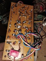
From your answers I understood that you gave me the voltages at the 5th and 6th point. There is very little left to be able to tell where the defect is. The answer is at points 1, 2, 3 and 4.btw if any of you can watch the video i willl be good 😀
oh ok i will measure those points later and post short video again. btw if i understand ,where i have 12v there should be 20+ v ?
thing you did where you put numbers on board thats what i understand 😀 now i know what to measureFrom your answers I understood that you gave me the voltages at the 5th and 6th point. There is very little left to be able to tell where the defect is. The answer is at points 1, 2, 3 and 4.
View attachment 1258178
View attachment 1258179
Hi sg97,
Okay, a couple things. I do not have time to watch videos, sorry. It's great some do. I can only go on what I see in text or a picture.
Your meter has terrible resolution and accuracy. If we want a voltage across a part, you have to measure directly across the part. So for example, measure across R4, not from "ground" to each side. Measure from a transistor emitter with your common (black) lead, the positive to the base and collector respectively for transistors. Measuring small voltage differences by going from ground to each point is a complete waste of time. To measure the circuit offset, yes you would measure from ground to that point (you see +12 VDC there).
Anyway, do your best. Also, don't fear something, respect it. Understand it, then you can avoid being hurt.
i can measure all those parts i already did for most of them and posted here , for transistors i was first measuring from c to b from bto e and so on.
Perfect.
sg97, I was just trying to give you general advice. Also, understand your meter has limits and you have to recognise this. The way I recommended you measure things is the way I do it. My meters are 6.5 digit, very accurate ones, but you still have to take measurements the right way. Also you have to consider noise and instability at various points, so if you want to know the voltage drop across something, measure across it.
"Ground" is a common reference point, but in an output stage it is often helpful to use the output (+12 VDC there) as your reference and measure the parts in the output from there to get a better picture of what things are doing. It depends on the circuit and what you are trying to do. That way shifting voltage and noise won't swamp your readings. This information is for everyone, not just you specifically.
that makes sense. btw i know that i dont have best equipment but i am trying to use what i have. voltages that i posted do change when i adjust the trim btw voltages that i posted are when trim was left not in the midle. it was a mistake xd i forgot to put it in the midle but only c from first transistor changes to 56v with that
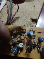
The first thing I would like to check is the connection between the emitter of the PNP transistor and the output of the amplifier. Contacts R4 with circuit?
You need to check both small transistors that give a signal to 2n3055 for communication with the board. Looks like there is a defect in one of them.

By the way, there is space on the board for another transistor, which was not soldered in its place.

You need to check both small transistors that give a signal to 2n3055 for communication with the board. Looks like there is a defect in one of them.
By the way, there is space on the board for another transistor, which was not soldered in its place.
Last edited:
I did that and there is not differenceI would unsolder these resistors on the side of the 83k and 92k tracks.
- Home
- Amplifiers
- Solid State
- transistor amp not working after shorting output