Chris, no problem. I'll try to remember to take some shots.
One thing we have found with those subs is when they go (in the blow up sense) they take a driver ( I think one is passive?) with it. The motors completely tear the "cone" from the surround. They are also sensitive to power fluctuations and dirty power in general. Unfortunately, that often comes with our line of work and not all shows can afford one of our 200Amp iso transformers.
One thing we have found with those subs is when they go (in the blow up sense) they take a driver ( I think one is passive?) with it. The motors completely tear the "cone" from the surround. They are also sensitive to power fluctuations and dirty power in general. Unfortunately, that often comes with our line of work and not all shows can afford one of our 200Amp iso transformers.
Hi imix500,
I'm guessing that the amps don't like voltage drops. That would be a Carver design signature if you will.

Extension cords and young fellas with too much power about right?
If you have a schematic, I could have a peek. They had some problems with under spec'd switching fets in a couple amps I know of from the Carver days.
-Chris
I'm guessing that the amps don't like voltage drops. That would be a Carver design signature if you will.
🙂 Yeah, I know. I spend years repairing different amps that operated under those conditions. Think Carabanna (Toronto), gas generators and Carvers. It's not pretty!Unfortunately, that often comes with our line of work and not all shows can afford one of our 200Amp iso transformers.
Extension cords and young fellas with too much power about right?
If you have a schematic, I could have a peek. They had some problems with under spec'd switching fets in a couple amps I know of from the Carver days.
-Chris
Hi Chris,
you would think so, but all it takes is an orchestra member (that's where we use these things most often) to swap it for thier precious fanny heater on a quad box labled "SOUND ONLY" and plug the sub into the nearest wall outlet.
We do power ground stacked M2D's with a Yamaha 5k gen set on each one around town quite often. Three power gound references (including foh power), one audio ground. We've been lucky.
I'll see if we have a schematic as well.
kartino said:Hi, Eva and MJJZ,
I gree with Eva, Mosfet are good for under 200V (for me!) and for you MJJZ, at high voltage the Rds on beetween bipolar and mosfet not a concern anymore, remember that this is HIGH VOLTAGE
Irony: 2 a : the use of words to express something other than and especially the opposite of the literal meaning 😉
PS. I agree with you that these things should be no-no for DIYer.
Ok, here are the pics of the Sunfire. I don't know how to do that nifty trick where the full size pics are all displayed one after another, so they are on photobucket...
http://i96.photobucket.com/albums/l190/imix500/IMG_0827.jpg
http://i96.photobucket.com/albums/l190/imix500/IMG_0828.jpg
http://i96.photobucket.com/albums/l190/imix500/IMG_0829.jpg
http://i96.photobucket.com/albums/l190/imix500/IMG_0830.jpg
http://i96.photobucket.com/albums/l190/imix500/IMG_0831.jpg
http://i96.photobucket.com/albums/l190/imix500/IMG_0832.jpg
http://i96.photobucket.com/albums/l190/imix500/IMG_0833.jpg
http://i96.photobucket.com/albums/l190/imix500/IMG_0834.jpg
http://i96.photobucket.com/albums/l190/imix500/IMG_0835.jpg
You guys are right though, no power transformer to speak of. Mains are rectified, filtered and sent onto the boards. Crazy stuff. The small transformer is for low voltage rails I belive.
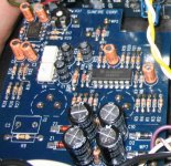
The pictures clearly show double ended half-wave mains rectification in order to get +-170V, and then two switching regulators producing the supply rails that fed a class AB amplifier.
Eva said:The pictures clearly show double ended half-wave mains rectification in order to get +-170V.
Hi Eva
I haven't come across that term before. Can you show us a schematic example.
Thanks
Rob
anatech, I was looking for Private Messages, but didn't see how I am to recieve them. I just looked in FAQ, and clicked on Inbox, and it says that the administrator has private messaging disabled.
Anatech, the reason I started this thread was because I had seen a magazine advertisement with a tower speaker. In the subwoofer compartment of it they said they had a 500W amp. They showed a real tiny circuit board.
I believe they said it was a carver sunfire design.
I also saw an add for a make of tower speakers which had front and back firing HF and MF drivers. It also had a side firing subwoofer. Again, there seemed to be a little tiny circuit board which they said was a 1000W amp.
I do not take this lightly at all. I have frowned on that approach. So I started this thread to see if anyone else has experience with these products, or anything else on the market which is designed like that.
imix500, those pictures are fantastic. Thank you.
Now in the adobe papers that anatech posted, Carver describes this system as using two active drivers.
In the pictures you posted, there is clearly one active driver and one passive driver.
So if I am understanding you, there is a small 60hz transformer, but that is for the input circuitry.
Then there is an optical coupler?
Then there is no high frequency transformer, no isolation of any type for the main power amplifier?
How about the driver and the enclosure. Does it look like the driver was designed to provide guaranteed isolation? How about the lead that feed the voice coil? How about the basket frame which in some failures could contact the voice coil?
Does the driver have a flat disc for a radiating surface, instead of a concave cone?
Could a user touch mounting screws or any part of the metal basket frame?
Does the grill cloth come off?
Do these units come with special warnings written on them? Any special warnings in the instruction book?
Do they have all of their approval stamps on the unit, like UL?
imix500
I continue to study you outstanding pictures.
This unit does have some real strong warnings on the back of it!
Looking at the edges of the panels where the drivers are, it looks like the panels might cover up the outer most part of the the driver basket and the cone surround.
Is the driver basket metal annodized?
Of course that is a giant and very heavy magnet. About 15lbs according to the Carver paper that anatech posted
It does look like the internal terminals to connect to the driver could have been designed for line voltages.
As far as using opto couplers, I would want to know more about that.
If this was a powered speaker that took a digital feed. Not PWM, but actually digital, then optical couplers would be no problem. But with analog or PWM, I would still be conderned about some signal degradation in band width or distortion.
I look at the biggest capacitors. You picture makes visible the notation of 200V, 1500uF. That is not much.
Now days all of these amps are using the output transistors to also provide power supply ripple regulation. For high power, there really is no other practical way.
This has lots of other capacitors which can totally filter the earlier stages.
There are also two good sized inductors, and some non-eletrolytic capacitors. That would look like a filter for the class D switching.
Interesting.
No, no one should try to copy this with an off the shelf driver, or with conventional mounting and enclosure techniques, or without a giant isolation transformer for trouble shooting, or without adequate knowledge of all saftey requirements.
zenmasterbrian said:
As far as using opto couplers, I would want to know more about that.
If this was a powered speaker that took a digital feed. Not PWM, but actually digital, then optical couplers would be no problem. But with analog or PWM, I would still be conderned about some signal degradation in band width or distortion.
Hi Brian
The chip adjacent to the opto-couplers is a quad jfet op-amp so I think the inputs are analog, not digital. Unfortunately, the type numbers of the opto-couplers are not visible so I can't comment on their performance in this role. Maybe imix500 could provide the type numbers.
Cheers
Rob
Hey guys, no prob. Glad to help. I will revisit the sub today (it's pretty easy to take apart) and try to answer the questions and get part numbers of the optos. I'll be doing this during my lunch break so if you guys need anymore info let me know by 1pm eastern.
Btw, I tried to get schematics but "The Sunfire Corporation" is very tight lipped about servicing these things, and they are ungodly expensive to fix. They won't even sell us spare drivers.
Hi imix500,
Those are great shots, thank you!. This may be line operated. The dance at UL and CSA must have been fun to watch. Of course there may be a PM-2.0 type power supply here as well. In that amp the mains were bridge rectified and they used a switching supply to derive the operating voltages.
At this point I would really love to see a schematic!
-Chris
Hi zenmasterbrian,
You should be able to message me. My mail is turned on, and you are not under moderation.
Hi imix500,
Yes they are scretive. Partially because we saw most shops destroy the regular Carver product even with the service information. The thought of the average tech messing around with downconverters and line operated gear would keep me up at night too. So I can't say that I blame them just because I want to know what they did.
Now I'm out of the loop. 🙁
-Chris
Anatech, the Class-D thread has been reopened.
But about PMs, I sent one to you and one to Jean-Paul. I have never seen any PM's sent to me, or even how I would recieve one.
About the Carver pictures:
I guess that what those pictures also tell us is that the heat sink has to be internal.
You can't depend on the thin layer of mica for your power mains isolation if your heat sink is on the back of the box.
Anyone seen the ads I saw for the tower speakers with little built in amps like that? They also looked like they were probably transformerless.
Ok, had some extra time before 9am this morning.
The optos are motorola
CNY
17-1
QC807
The input board also has a MC3400 and TL072.
The output transistors are Toshiba 2SC3281 and 2SA1302.
The optos are motorola
CNY
17-1
QC807
The input board also has a MC3400 and TL072.
The output transistors are Toshiba 2SC3281 and 2SA1302.
Hi zenmasterbrian,
-Chris
That happened last night.Anatech, the Class-D thread has been reopened.
I sent you a PM in reply. It arrives as standard email to the address you specified. Check your junk folder. I have had my ISP block the mail before. That is annoying.But about PMs, I sent one to you and one to Jean-Paul. I have never seen any PM's sent to me, or even how I would recieve one.
Never! That's a life and death issue.You can't depend on the thin layer of mica for your power mains isolation if your heat sink is on the back of the box.
No, but if they are copies, they may be dangerous. Possibly without UL/CSA approval.Anyone seen the ads I saw for the tower speakers with little built in amps like that? They also looked like they were probably transformerless.
-Chris
- Status
- Not open for further replies.
- Home
- Amplifiers
- Power Supplies
- transformerless amps?