Hi imix500,
Standard Carver parts lineup.
Optocouplers can be biased in class "A" and modulated to transmitt analog information. They could also use an FM system or another modulation scheme. This is greatly simplified as we are talking subwoofer frequency ranges.
-Chris
Standard Carver parts lineup.
Optocouplers can be biased in class "A" and modulated to transmitt analog information. They could also use an FM system or another modulation scheme. This is greatly simplified as we are talking subwoofer frequency ranges.
-Chris
rpapps said:
Hi Eva
I haven't come across that term before. Can you show us a schematic example.
Thanks
Rob
Rob,
The term EVA is referring to is basically the front end of almose every switching supply that is not actively PFC'ed. Going something like this:
AC -> AC line filter (Many times it is optional) -> Diode Bridge (double-ended half-wave if in the US or any location with 100-125V mains) -> Bulk Filter Capacitors -> DC-DC PWM section -> Regulated DC Output voltage(s).
A few notes here, (oh, and BTW, those are outstanding shots), I said the AC filter was many times optional, not because regulatory agencies have relaxed their standards, but because many of the cheap Chinese and other Asian Mfrs like to cut corners, and their poor business accountability really show itself here.
Reference DCPreamp's post:
"Not too long ago, I had the privilege of working with an Electronics Engineer from China. He was absolutely brilliant and had vast amounts of experience from all over the world in areas including military RF, test equipment, power supply design, computer monitor design, and more.
I found this disturbing and always question the safety of everything. I have also questioned the safety of many other AC power products produced in China including high-end audio products, powered speakers, and others. I always recommend using caution when purchasing cheap or too-much-performance-for-the-cost products, and especially ones from Asian countries, although that’s virtually impossible to avoid. I wouldn’t put too much faith into UL and CE stamps either. Stick with name-brand products and those from established manufacturers."
Double-ended Half-wave rectified: This is essentially a diode-capacitor voltage doubler, yielding ~+330VDC, or ~+/-165VDC, if the AC Neutral is referenced as Ground. Then the (+)-going diodes will collect the (+) half of the AC Sinewave, and the two (-)-going diodes will collect the (-) half of the AC Sinewave. Then the two 1500mF 200V Electrolytics will be connected in series across the rectified hi-voltage DC, and their centerpoint will be connected to AC Neutral, The diode bridge shown in your pics has its two AC terminals connected together for two reasons: 1) it doubles the current-carrying capacity of the diode bridge, and 2) since this product appears intended for the North American Market, it should never see 220-240VAC. If it did, then the AC Neutral connectig to the Bulk Cap. center-point would have to be connected to other AC terminal of the rectifier bridge, thus yielding the same +330VDC, with the ground still at the bulk cap centerpoint. Still with me? 😀 😕
Anyway, with all that said and done, like EVA and all the others, it bothers me that the DC-DC Tracking downconverter provides no galvanic isolation between the (+/-) DC outputs and the AC line input. I pretend to have no extensive knowledge of how the Carver folks set this up, but it would seem to me that almost the same thing could have been achieved using a conventional DC-DC PWM section that is transformer-isolated, like in almost every AT & ATX psu on the market, only scaled up to meet the "2.7kW" power demands.
OK, now I'm starting to confuse myself, so I'll pause here to catch my breath and digest some of this stuff. (whew!)
Steve
Hi Steve,
Carver designs usually are isolated from the AC mains with a transformer. This is a new one for me if there is a connection. The downconverter itself is only a step down / tracking scheme. It was never designed as a replacement for a standard power supply, just a fancy regulator.
Unless I see a schematic diagram, I will not know for sure.
-Chris
Proper isolation techniques are the key for such a setup to be safe. Remember that almost every electric appliance in our kitchens is full of mains-live elements like heaters, coils, motors, valves, pumps, triacs (using the chasis as a heatsink), thermostats, switches, etc... yet we regard that stuff as safe. Furthermore, water is involved in the working of some of them!!
BTW: Not suitable for the average DIYer anyway.
BTW: Not suitable for the average DIYer anyway.
zenmasterbrian said:Anatech, the Class-D thread has been reopened.
You can't depend on the thin layer of mica for your power mains isolation if your heat sink is on the back of the box.
The "thin layer of mica" may block 5000 V quite easily. However, it has to be thick in order to reduce capacitances from the transistors tabs to the heatsink in order to keep EMI under control.
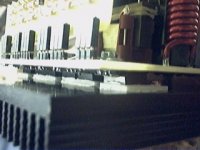
Aluminium oxide (a white ceramic substance) is routinely used in place of mica for class D applications. See picture :
Attachments
Hi Chris,
That's what I thought, especially from a well reputed manufacturer like Bob Carver. However, when I look closely at Rob's pics, I see the AC Neutral (white wire) connecting directly to the centerpoint junction of the two 1500mF Caps. I also see that tghe AC Hot (black) going through a fuse socket and going to one end of the diode bridghe.
I do like the concept of using PWM to regulate (+/-) final outputs, but not at the expense of safety. Also, I'm suprised that ol' BC didn't go the PFC-Full-bridge PWM route. He would achieve two things simultaneously: 1) galvanic isolation and easier safety acceptance from all the world's regulatory agencies, and 2) automatic compatibility with all AC mains from 85-264VAC, making it suitable for worldwide export.
Imagine what would happen if someone plugged it into a 220-240VAC mains.


 Just my $0.02 worth. Thoughts?
EVA- good point on the mica thing. How is it you think of all the things most of the rest of us miss? 😉 nice pic, too.
Steve
That's what I thought, especially from a well reputed manufacturer like Bob Carver. However, when I look closely at Rob's pics, I see the AC Neutral (white wire) connecting directly to the centerpoint junction of the two 1500mF Caps. I also see that tghe AC Hot (black) going through a fuse socket and going to one end of the diode bridghe.
I do like the concept of using PWM to regulate (+/-) final outputs, but not at the expense of safety. Also, I'm suprised that ol' BC didn't go the PFC-Full-bridge PWM route. He would achieve two things simultaneously: 1) galvanic isolation and easier safety acceptance from all the world's regulatory agencies, and 2) automatic compatibility with all AC mains from 85-264VAC, making it suitable for worldwide export.
Imagine what would happen if someone plugged it into a 220-240VAC mains.
Just my $0.02 worth. Thoughts?EVA- good point on the mica thing. How is it you think of all the things most of the rest of us miss? 😉 nice pic, too.
Steve
I have seen that 120V doubler circuit connected to 230V several times in PC power supplies. Nothing special happens most times because the fuse blows instantaneously, both due to the increased inrush current and due to the fact that the capacitors start to act as a short (crowbar effect) when they are charged above 200V.
Occasionally the capacitors may vent, but the fuse should not live for enough time to allow significant pressure buildup inside the cans (it should be conservatively sized).
Occasionally the capacitors may vent, but the fuse should not live for enough time to allow significant pressure buildup inside the cans (it should be conservatively sized).
Hi Eva,
The problem with relying on mica insulators for this is the workmanship of the next technician. You have to make the assembly inherently safe (within reason).
Hi Steve,
The neutral being used as the center tap does not bother me at all. It's the primary circuit still. There may be isolation further along, but I can see it and I don't want to make an assumption on this.
-Chris
Chris,
It's not the cap-diode thing right off the AC Mains that bothers me (all pc supplies start out this way), but the lack of galvanic isolation down the road. A true transformer really would help allay these misgivings. Ol' Bob really must'a had his dancin' shoes on for those cert's! 🙂 If they (CAS and UL, at least) really knew the danger a the lack of galvanic isolation posed, they'd a' never certified. I know I wouldn't have.
I wonder of BC posts or even watches here.
Steve
Hi Steve,
I'm hoping there is at least a high frequency transformer that we missed somewhere. If not, this would be very out of character for Bob Carver.
I would have loved to see that dance (at UL and CSA).
-Chris
I'm hoping there is at least a high frequency transformer that we missed somewhere. If not, this would be very out of character for Bob Carver.
I would have loved to see that dance (at UL and CSA).
-Chris
When I first heard of the Dual Tracking Downconverter in the late 80's-early 90's, Initially I thought it was some sort of SMPS, albeit suited for audio purpses. As I started reading the white paper (for the life of me, I can't find it anywhere 🙁 ), I thought it might be a standard 50/60Hz line Xfmr, big smoothing caps and a bi-polar switching buck regulator. Not bad, I thought. At least it gets rid of the need for massive heatsinking for the Amplifier's outputs (as stated and shown in the white paper). I remember it saying because the tracking downconverter allowed only 6-9V across the output transistors, this enabled the amp's output sections to deliver the full 6 x 20A (6 NPNs & PNPs, each rated at 20A) of the transistors' collector current ratings, because of the significantly increased SOA. It never said there was an isolation xfmr, nor did it get specific about the bulk filter caps, and this raised a red flag in the back of my mind, but I never really ruminated on it much. The pics in the whiter paper only showed the Amp section, the downconverter card, complete with switching transistors. The white paper got very specific on how the regulators worked, but never specifically mentioned a line isolation transformer- it was always implied.
After following and now posting on this thread, all of my suspicions are confirmed. Bob, if you're reading this, please comment!
Steve
After following and now posting on this thread, all of my suspicions are confirmed. Bob, if you're reading this, please comment!
Steve
Given the amount of power managed and the size of the speaker and the enclosure, a conventional mains transformer would just not fit inside the box. Even a suitably rated SMPS won't fit, I think.
Also, any off-line SMPS would require the primary side switching transistors (which are live) to be attached to the face plate for proper heatsinking anyway.
Finally, if a washing machine or a dishwasher can met safety regulations, such a subwoofer should also do with proper isolation techniques. It may be a pity for conventional technicians, though, because an isolation transformer is required for servicing (as it is for TVs and other SMPS-fed stuff anyway).
Hi Eva,
That is my concern. They withhold information to attempt to force service into the proper channels, but we have a class of technician who is not well trained that will attempt the repair anyway. Those are the people I worry about.
-Chris
That is my concern. They withhold information to attempt to force service into the proper channels, but we have a class of technician who is not well trained that will attempt the repair anyway. Those are the people I worry about.
-Chris
anatech, thanks for enlightening me about PM's. I thought they were recieved here. I didn't know they resulted in emails.
( What is SMPS? )
( What is SMPS? )
http://www.soundstage.com/revequip/revel_b15.htm
Revel Performa B15
Claims it has 1000W amp in such a small box. That with the unusual look of the driver makes me suspect that it could be transformerless.
Revel Performa B15
Claims it has 1000W amp in such a small box. That with the unusual look of the driver makes me suspect that it could be transformerless.
Hi Brian,
One wonders how much power is really available at the outlet. Also, could this be some kind of peak power rating. The voice coil will have to dissipate most of this energy has heat. So the former material, glue type, diameter and length come into play. Also gap width and venting. The bulk of the heat will be radiated by the magnet assembly. I have my doubts on the usefulness of a 1000W woofer. I would think an efficient woofer that does not require this much power for the same acoustic output might be superior. Putting it in the correct sized box would help, but the shipping would be murder.
-Chris
Basically, a switch mode power supply. Eva is an expert on this subject. There are many other members that are also well versed on this subject.( What is SMPS? )
This amp may use a switch mode power supply and some type of switching amplifier, class "D".Claims it has 1000W amp in such a small box.
One wonders how much power is really available at the outlet. Also, could this be some kind of peak power rating. The voice coil will have to dissipate most of this energy has heat. So the former material, glue type, diameter and length come into play. Also gap width and venting. The bulk of the heat will be radiated by the magnet assembly. I have my doubts on the usefulness of a 1000W woofer. I would think an efficient woofer that does not require this much power for the same acoustic output might be superior. Putting it in the correct sized box would help, but the shipping would be murder.
-Chris
This is an interesting thread.
Not to get off topic, but I have a request for EVA and other members experienced with SMPS design: Please recommend some resources for SMPS design information. What are some good books or websites on this topic?
Not to get off topic, but I have a request for EVA and other members experienced with SMPS design: Please recommend some resources for SMPS design information. What are some good books or websites on this topic?
- Status
- Not open for further replies.
- Home
- Amplifiers
- Power Supplies
- transformerless amps?