Just to answer to 45.
your post:
Again your conlcusion is specific to your cases. It is not general!! -------Is not my case , it is always the same.------------
See here for example:
Output Transformers | Tubelab
this reference are test with triode connection ( easier than pentode due a much lower internal impedeance of tube) , UL (= feedback), cathode feedback ; these test aren't so clear for the trafo (in my opinion).
Then, regarding the test on ETF.
I am surprise that someone show this method as the reference for the OT tests.
The test set is very poor and the conclusion are an artefact.
There is a strange shape of distortion from 10 Hz to 1000 Hz where all the trafo show a similar slope of distortion.
Is it possible? Or something is wrong?
Is it possible that for a large stuff ( very few execption) of dut the armonics are almost the same?
Bye
Walter
PS.
In the second generation I could increase the insulation and further reduce the capacitance. 😉
In the second generation I could increase the insulation and further reduce the capacitance. 😉
Then, regarding the test on ETF.
I am surprise that someone show this method as the reference for the OT tests.
The test set is very poor and the conclusion are an artefact.
There is a strange shape of distortion from 10 Hz to 1000 Hz where all the trafo show a similar slope of distortion.
Is it possible? Or something is wrong?
Is it possible that for a large stuff ( very few execption) of dut the armonics are almost the same?
Bye
Walter
It's at 0.5W. Have you considered it?
Test Setup
Hi, esltransformer,
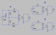
1) What test setup do you use to test frequency response of push-pull (not SE) output transformers?
Menno van der Veen recommends setup #1, which somewhat resembles real world conditions. However, much simpler setup #2 and #3 produces very similar results (I tried all 3 just to be sure). I would be glad to know your experience.
2) Few notes about transformer distortions.
I have distortion coefficients THD% = F(B, DC BIAS) for GOSS and nickel cores made by G.S.Tsykin. His 400-pages book "Low frequency transformers" published back in 1955 is a Russian bible of transformer design. Since book printed back in 1955, measurements probably made at the end of 194x with B only up to 1.2T (for GOSS) and 0.9T (for nickel iron). Compared to today's alloys, the numbers had to be divided by a factor of 20 - 40.
"Audio Transformer Design Manual by" Robert G.Wolpert, 1984, also have similar data, albeit also outdated, and not comprehensive as the one generated by G.S.Tsykin. The last made charts/tables for harmonics calculation from 2nd to 5th, with different levels of DC bias.
Have you seen any similar data, no older then 10 - 15 years?
Hi, esltransformer,
1) What test setup do you use to test frequency response of push-pull (not SE) output transformers?
Menno van der Veen recommends setup #1, which somewhat resembles real world conditions. However, much simpler setup #2 and #3 produces very similar results (I tried all 3 just to be sure). I would be glad to know your experience.
2) Few notes about transformer distortions.
I have distortion coefficients THD% = F(B, DC BIAS) for GOSS and nickel cores made by G.S.Tsykin. His 400-pages book "Low frequency transformers" published back in 1955 is a Russian bible of transformer design. Since book printed back in 1955, measurements probably made at the end of 194x with B only up to 1.2T (for GOSS) and 0.9T (for nickel iron). Compared to today's alloys, the numbers had to be divided by a factor of 20 - 40.
"Audio Transformer Design Manual by" Robert G.Wolpert, 1984, also have similar data, albeit also outdated, and not comprehensive as the one generated by G.S.Tsykin. The last made charts/tables for harmonics calculation from 2nd to 5th, with different levels of DC bias.
Have you seen any similar data, no older then 10 - 15 years?
Attachments
My last OPT, made with the same EI 155 (EI 114 for eu), with a core area of 38x38, double insulation 0.25 mm primary wire (about 0.3 mm) has more than 3800 turns, bobin-epoxy-wire-epoxy-polyester-epoxy-wire...wire-epoxy-NOMEX winding scheme for each winding, 10 primary windings and 8 secondary windings oversized with 0.65 mm wire all paralleled and even leftover me window enough to many more primary layers, so no much problem for about 4300 turns.
Even I could make it without changing secondary wire, nor sixteen 0.4 mm NOMEX insulation. 😉
Sorry, it's 0.45 mm, my bad, I'm getting old, that was for another OPT. 😀
Sorry, it's 0.45 mm, my bad, I'm getting old, that was for another OPT. 😀
Still not enough! How many layers assuming 8 secondaries? With .516 size (i.e. 0.45 mm wire + double insulation) you can put about 100 turns per layer, assuming the winding is well executed and max use of horizontal space is achieved.
3800:100 = 38 not good for 300B. If two layers in series 3800:200=19 is ok but copper loss is high (about 0.6 ohm which translates into 210 ohm at best without adding the primary copper loss yet!). Ratio won't change significantly if you use less horizontal space has one has to have good coupling....
The height taken by the secondary only will be more than 8 mm. Even if you use single insulation wire you will only save about 0.3 mm. The ratio will be lower and power loss similar.
And 10 primaries with 3800 +/-50 turns with 0.3 total wire size? Don't sound right on that coil former. Bad coupling and/or distorted f.e.m easy! However using the same criteria of the secondary (otherwise will only be worse) it can't be anything far from 22 layers (21 or 23 just as bad if not worse!). How you divide them symmetrically respect to the secondaries into 10 primaries? Mhhhh....
And even so the DC resistance would be in the region of 300 ohm! About 500 ohm for less than 2.9K primary impedance. Not really great....
Still 22 layers with 0.3 mm will take just shy of 7 mm height. I can't see where you put all that insulation and still you say can add 500 turns!!!???!!!
With the EI-120 standard coil former I use -that has basically the same winding height and is a bit wider than EI114 which is also not very common this side of the ocean....- the total height of the winding is 15 mm and one has to do it very carefully to stay within that value. Only about 1 mm is left from touching the core.
Last edited:
Still not enough! How many layers assuming 8 secondaries? With .516 size (i.e. 0.45 mm wire + double insulation) you can put about 100 turns per layer, assuming the winding is well executed and max use of horizontal space is achieved.
3800:100 = 38 not good for 300B. If two layers in series 3800:200=19 is ok but copper loss is high (about 0.6 ohm which translates into 210 ohm at best without adding the primary copper loss yet!). Ratio won't change significantly if you use less horizontal space has one has to have good coupling....
The height taken by the secondary only will be more than 8 mm. Even if you use single insulation wire you will only save about 0.3 mm. The ratio will be lower and power loss similar.
And 10 primaries with 3800 +/-50 turns with 0.3 total wire size? Don't sound right on that coil former. Bad coupling and/or distorted f.e.m easy! However using the same criteria of the secondary (otherwise will only be worse) it can't be anything far from 22 layers (21 or 23 just as bad if not worse!). How you divide them symmetrically respect to the secondaries into 10 primaries? Mhhhh....
And even so the DC resistance would be in the region of 300 ohm! About 500 ohm for less than 2.9K primary impedance. Not really great....
Still 22 layers with 0.3 mm will take just shy of 7 mm height. I can't see where you put all that insulation and still you say can add 500 turns!!!???!!!
With the EI-120 I use -that has basically the same winding height and is a bit wider- the total height of the winding is 15 mm and one has to do it very carefully to stay within that value. Only about 1 mm is left from touching the core.
Your crystal ball doesn't work again. 😀
Where did I said that mine is an OPT for 300B? 😕
The point was show you that, if you know how, more than 4000 turns fit comfortably with that particular core, even with an oversized secondary.

BTW. For a 300B is even easier. 😉
Hope I don't need explain you why.
I am not willing to an endless fight, thread after thread as is your style, so addio. 🙂

Last edited:
Popilin do you read/understand what you write????Your crystal ball doesn't work again. 😀
Where did I said that mine is an OPT for 300B? 😕
The point was show you that, if you know how, more than 4000 turns fit comfortably with that particular core, even with an oversized secondary.
BTW. For a 300B is even easier, due to lower primary impedance. 😉
Hope I don't need explain you why.
This what you wrote:
Zp=3500 Ω Zs=8 Ω ip=120 mA fo=18 Hz W=30 W
300B or not is not even relevant. The impedance YOU assumed is 3.5K!
So even worse if you have to get this ratio with those wires, turns and coil former!!!!!!!
Make some transformers for real first.....
Popilin do you read/understand what you write????
Do you???
10 primary windings and 8 secondary windings is really bad choice in general unless you are using a double cave (so it is 3+2 and 3+2) which leaves even less space for the winding but will be a poor choice anyway because your leakage inductance will be very high!
So 10 + 8 = (3+2) + (3+2) 😕
And interleaving increased leakage inductance? Interesting.

The winding volume is not a variable you can decide.
Sure, same as core area. 😀
The purpose of my few scribbles is to illustrate the point that the OP numbers are totally possible
Conclusion: As I said before, a lower primary impedance make things easier and the open poster did a superb design with its OPT, and you are only capable to criticize them.
So 10 + 8 = (3+2) + (3+2) 😕
And interleaving increased leakage inductance? Interesting.
It's not the interleaving is the strange way you define things which makes me think you are pretty inexperienced. 3+2 and 3+2 was just a trap and referred to the primary only to see your reaction! It's too late now to answer.....
If you had an intermediate flange it would be 5 primaries and 4 secondaries per half with the two outer primaries with half turns respect to the inner ones (This thing I told you sometime ago in 3d about interstage as you never thought about it...).
In this case something geometrically good could happen, the ratio gets closer to 3.5K, the leakage inductance gets reasonable but the power loss is still highish. I simply can't see any practical advantage in comparison to EI 120/50 which is MILES better! 1.3T for the nominal power at 30Hz is poor! Practical advantage also means how easy is to find....
After this theorical discussion, VERY unfortunately you won't have any space left for any reasonable insulation with those wires!
Look at post no3.
And telling physical facts HiB, M6, C-core, EI is just normal, not specially criticism more a design argument.
ESLtransformer I didn't have any bad approach in the beginning. Just trying to understand your figures. .
Look further and see what you concluded at some point about a number of things. Normal is also Hi-B C core. Depends on whether you see the glass of water half empty or half full! It depends on how you use them.
All transformer experts here but none with a real cue on what it should be supposed to do in the REAL world!!
It is assumed that transformer experts must have reasonable handling of elemental algebra, at least.
What is this? REAL world math? 😀
So 10 + 8 = (3+2) + (3+2) 😕
And interleaving increased leakage inductance? Interesting.
It's not the interleaving is the strange way you define things which makes me think you are pretty inexperienced. 3+2 and 3+2 was just a trap and referred to the primary only to see your reaction! It's too late now to answer.....
Ah, silly me, it was a psychological experiment, very clever. 😀
If you had an intermediate flange it would be 5 primaries and 4 secondaries per half with the two outer primaries with half turns respect to the inner ones
Well, this makes more sense. 😉
In this case something geometrically good could happen, the ratio gets closer to 3.5K, the leakage inductance gets reasonable but the power loss is still highish. I simply can't see any practical advantage in comparison to EI 120/50 which is MILES better! 1.3T for the nominal power at 30Hz is poor! Practical advantage also means how easy is to find....
I honestly hope your papers are not written thereby.
About cores, C cores are far superior, as advantages over EI cores I will mention only two
-With GOSS, magnetic field B direction is coincident with direction of rolling.
-You can use ridiculously thin lamination, e.g. 0.025 mm.
After this theorical discussion, VERY unfortunately you won't have any space left for any reasonable insulation with those wires!
Theorical discussion

If sixteen 0.4 mm NOMEX insulators isn't enough for you...
As insulator, NOMEX has the advantage that has a very low dielectric constant and this help to decrease interwinding capacitance, vertical sectioning also. 😉
This goes like an advice, because you have redeemed with the OP, and that makes me happy. 🙂
It is assumed that transformer experts must have reasonable handling of elemental algebra, at least.
What is this? REAL world math? 😀
...cut...
If sixteen 0.4 mm NOMEX insulators isn't enough for you...
I am afraid Popillin as I told it's too late for strutting now! Buy a standard EI-114 coil former and see for real how much height you have and how much you need for your theorical transformer.
If you already have more than 15 mm (can you do this math now?) for the above "improved" transformer that only includes the wire see how much insulation you can put and also find extra space for additional 500 turns! Simply there is no space.
One practical thing....if I wanted to save on something I would use E120/40 at least as I already have this size and don't need to buy E114 laminations. Where is the advantage of 38x38 in comparison to 40x40???????
But that's not the point. The point is why should I "emulate" a C-core when it is not possible?
If I wanted to save on size I would make a completely different choice: same specs C-core, less power EI-100. Easy.
Again, make some transformers for real.....
In real live the best transformer companies use c-core for there "high end" series.
Yes, but have you ever thought that it could be more convenient also for reasons that go beyond effective performance? On one side it looks cooler for sure and more appealing (so it's also easier to justify the higher price) on the other side if it is ligher for certain specs it is also cheaper to ship.
As I said in the beginning DIY is different.
I am a diy 🙂 , sometimes i sell a transformer but i have limited time.
Most time (read costs) is winding a transformer, the core is just peanuts.
Btw developing is also costly.
Most time (read costs) is winding a transformer, the core is just peanuts.
Btw developing is also costly.
Yes, but have you ever thought that it could be more convenient also for reasons that go beyond effective performance? On one side it looks cooler for sure and more appealing (so it's also easier to justify the higher price) on the other side if it is ligher for certain specs it is also cheaper to ship.
As I said in the beginning DIY is different.
Last edited:
I am a diy 🙂 , sometimes i sell a transformer but i have limited time.
Most time (read costs) is winding a transformer, the core is just peanuts.
Btw developing is also costly.
Yes I know. Most of the price you pay is for work. Developing is just at the beginning, once you get some experience you also find shortcuts and can estimate final specs with very good approximation.
In my case I easily find highest quality E+I. Hi-B C core difficult unless I buy tons. It's not the price. Just like Walter here. I am not a seller either.
I am afraid Popillin as I told it's too late for strutting now!
Don't care, I left high school a long time ago. 😀
Buy a standard EI-114 coil former and see for real how much height you have and how much you need for your theorical transformer.
If you already have more than 15 mm (can you do this math now?) for the above "improved" transformer that only includes the wire see how much insulation you can put and also find extra space for additional 500 turns! Simply there is no space.
No need to buy, I have a lot of EI 114 standard coil former, polypropylene with mineral filler, has 1.7 mm wall thickness, and 16 mm depth, but you forgot a little detail, if you take the trouble to read post#114, you will see that I use 0.05 mm polyester between layers, when +B isn't very high, and being in mind that I use double insulation polyesterimide resin, 180ºC thermal grade copper wire, in extreme cases I wouldn't put that polyester, and obtain more space for wire, about 1.2 mm in tis case, more than enough. 😉
A little trick: after finish a winding, I put wood sticks with 0.05 mm mylar, because epoxy pours, and press to the nominal winding high for about three days and it works very well, Hashimoto-san trembles! 😀
One practical thing....if I wanted to save on something I would use E120/40 at least as I already have this size and don't need to buy E114 laminations. Where is the advantage of 38x38 in comparison to 40x40???????
But that's not the point. The point is why should I "emulate" a C-core when it is not possible?
If I wanted to save on size I would make a completely different choice: same specs C-core, less power EI-100. Easy.
Lucky you, can obtain lamination that you want, in this part of the world isn't so easy, I must be lucky if I can obtain mediocre standard Italian M6 lamination, only few measures, usually bad cutted, so I buy double than necessary and later select the best ones, and wash one by one with a solvent to remove the oil.

I have about 17 Kg of EI 120, but is so bad cutted, that is almost unusable, unless I take the trouble of sanding them. 🙄
BTW, be careful, bigger isn't always better, a bigger core needs less wire, but I prefer copper losses than core losses.
Again, make some transformers for real.....
Don't care, I need not prove anything. 😎
Last edited:
#114, you will see that I use 0.05 mm polyester between layers,
Popillin I repeat the question: do you think you can fool people this way?
It's not enough anyway. You need 2 mm excluding the NOMEX and the additional 500 turns that now have disappeared!!!!!
To get a decent transformer you need to do 24 layers (80 turns each) for the primary divided as 3+6+6+6+3 and 16 layers (47 turns each) 4+4+4+4 for the secondary for each half. So the primary would have 1920x2=3840 turns as you wish. This would be an ideal layout for minimal leakage inductance...if the winding is well executed.
Only this way the secondaries can be all in parallel as you wrote (because the 4 layers of each secondary will be in series for 188 turns in total to give a sensible ratio) and you would get just below 0.6 ohm for the DC resistance. High power loss but still acceptable.
For the last time...there is no space even with you minimal insulation! Even if I do not consider the NOMEX and the additional 500 turns!!!!!!!!
Last edited:
- Status
- Not open for further replies.
- Home
- Amplifiers
- Tubes / Valves
- transformer test