Thanks M.Gregg, yes, I can see the advantage of the mosfet B+ voltage dropper.
I know have a 180R 10W as my first resistor in PSU. I have taken your advice and moved this to its own place i.e. not soldered directly to first cap or second cap. Then I have made a new tag board which sits two 390R resistors. The B+ splits into this and both resitors have a 47uf cap to ground for a final bit of smoothing.
The 180R still gets red hot...
However, I think I've realised my mistake, I just don't want to admit it yet, I need to make a new aluminium plate for my valves as you can only squeeze half a valve between the pairs for each channel.... they are too close and this is causing unacceptable heat after an hour of running....
this means cutting all new holes for the valve sockets and moving all my components underneath.... not sure if I can continue but I will!
Thanks for all your help
S
Just a thought..
Your 10W 180...whats the current through it....what happens if you series two at 100 10W (in place of it).....<<look at the dissipation just for fun..
Regards
M. Gregg
Your 10W 180...whats the current through it....what happens if you series two at 100 10W (in place of it).....<<look at the dissipation just for fun..
Regards
M. Gregg
Last edited:
Just for interest,
Looking at the 180 ohm..you would get the same effect with two Fet stages..
Heres another thought for you...what would happen with four (series) 10W 50 Ohm..look at the dissipation..<<<Its just for fun..
Don't get tempted to cut the wattage rating of the resistors to the bone..keep the resistors high wattage (10W) they can dissipate more heat..
with the slight reduction in B+ the OP tubes should run cooler as well. Distance from the top plate will also help..heat rises. (a pad of holes in the top plate above the power resistors is another idea)<<<doing this will use the heat from the resistors to "drive" air flow in the chassis. In extreme cases I have seen resistors mounted in their own enclosure vented top and bottom so the heat can not travel under the top plate<<<here is a trial you could do for fun how hot does it get if the resistors are not in the chassis? Ie what is causing the heating of the chassis (is it the resistors or the tubes) Be careful remember its B+!
I would not modify any chassis work until you are sure you have it working as you want it...no good hacking at a new top plate..
The planning is so important..research <<at least then you get only minor problems...The main problem is B+ voltage level. Possible sag and heat. (as long as bias is correct or lower than the OP tubes can dissipate)
Regards
M. Gregg
Last edited:
Mounting resistors with holes in the top plate for ventilation is easy.
Just mount some tag board/strip each side of the holes and solder the power resistors between so the holes are above them in the top plate..if thats not enough put some aluminium around them like a box no bottom just the sides like a chimney so the heat can only go up not across the chassis<< lots you can do..these are only suggestions..
Really over kill for this kind of project...however if you have to work with what you have got then you use/do what you can..🙂
You need to know..is the heat from the power resistors, the valves or the power transformer on over load...so hang the resistors off the table on wires<<be very very careful b+<<is the chassis cool under these conditions<<if its not you need to think again..
Time to shut up again.. 😀..let us know how you get on.. If all else fails bolt high power resistors on a heat sink with the fins outside the chassis<<remember to earth the heatsink! <<its going to be rather HOT!
Regards
M. Gregg
Last edited:
One other thought..
You have vented the top of the chassis..so how much inlet of cool air do you have at the bottom of the chassis...if there are holes in the bottom are they placed directly under the power resistors (that have holes above for ventilation)and Op section?
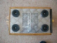
Like this example..(Pics have been posted before)
Its probably easier to use mesh plate..depends on what your doing..Think about where your venting and use the heat to advantage..make it move the air the way you want.
Think about the inside of the chassis as a building with equipment in how would you ventilate it for maximum effect..
All top plates bottom plates etc should be bonded to earth..(Safety)
Regards
M. Gregg
You have vented the top of the chassis..so how much inlet of cool air do you have at the bottom of the chassis...if there are holes in the bottom are they placed directly under the power resistors (that have holes above for ventilation)and Op section?
Like this example..(Pics have been posted before)
Its probably easier to use mesh plate..depends on what your doing..Think about where your venting and use the heat to advantage..make it move the air the way you want.
Think about the inside of the chassis as a building with equipment in how would you ventilate it for maximum effect..
All top plates bottom plates etc should be bonded to earth..(Safety)
Regards
M. Gregg
Attachments
Last edited:
OK, my 180R is passing approx 110mA of current (V=IR) = approx 20V drop
If I use two 100R's in series then each should drop approx 11V
Power being dissipated through each 100R = 11 * .110 = 1.21W....
Power dissipated through using single 180R = 20 * .110 = 2.2W
then why is my 180R too hot to touch after 20mins of operation?
S
If I use two 100R's in series then each should drop approx 11V
Power being dissipated through each 100R = 11 * .110 = 1.21W....
Power dissipated through using single 180R = 20 * .110 = 2.2W
then why is my 180R too hot to touch after 20mins of operation?
S
2.2W is a lot of power to dissipate from a small area.
That small area requires a big temperature differential to get rid of all that heat.
That small area requires a big temperature differential to get rid of all that heat.
OK, my 180R is passing approx 110mA of current (V=IR) = approx 20V drop
If I use two 100R's in series then each should drop approx 11V
Power being dissipated through each 100R = 11 * .110 = 1.21W....
Power dissipated through using single 180R = 20 * .110 = 2.2W
then why is my 180R too hot to touch after 20mins of operation?
S
Something is wrong check your figures..😕....is your measured voltage drop correct under load? (sag)
See how hot it is without playing music just sitting there!
PS you should not be touching a B+ resistor with your fingers<<<if the insulation fails you will get a shock..2watt can seem quite warm..but not melting solder etc..
Regards
M. Gregg
Last edited:
If your figures are correct..
If you are sure..then its 2Watt..and you need to work on the venting etc..Then again this is now about how hot the power Tx runs..and chassis..
So how hot is the power Tx? and chassis..What plans do you have to get efficient venting?
Regards
M. Gregg
If you are sure..then its 2Watt..and you need to work on the venting etc..Then again this is now about how hot the power Tx runs..and chassis..
So how hot is the power Tx? and chassis..What plans do you have to get efficient venting?
Regards
M. Gregg
Thanks for the concern, just to let you know that my B+ is bleeding to approx 5 volts in 10 - 15 seconds and then it dwindles down slowly. I am making sure it is almost all gone before I'm touching the resistors to see how hot they are!
Had to replace a small fixed pot that I use to bias the ccs to the diff amps. Was probing around and shorted cathode of triode to pentode screen!!
Back up and running, even dug out my old gigaworks dac that i built with UTC A20 transformers to listen to tonight. Had Amp upside down which was a bit unfair to test seeing as valves are stuffed towards the ground. Ran the amp for a few hours and the transformer was 'almost' too hot to touch for more than 10 seconds but not quite. Am looking forward to digging out my 12b4 linestage that I also built... (bet your wandering how I managed to build all that stuff - so am I!!)
Anyways, back on track.... ventilation... will take your suggestions on board and go about working out how I may use the thermal rising affect to my benefit.
cheers Stuart
Thanks for the concern, just to let you know that my B+ is bleeding to approx 5 volts in 10 - 15 seconds and then it dwindles down slowly.
Anyways, back on track.... ventilation... will take your suggestions on board and go about working out how I may use the thermal rising affect to my benefit.
cheers Stuart
Stuart,
Remember the B+ discharge time is the result of the heaters being hot after power off...so the B+ will discharge quite fast..however if ever your B+ is up with the heaters not working for some reason..it will be a lot slower and will catch you out if you are not expecting it...so don't worry about having quite high value bleeders its OK because it will come down over a period...just always remember test before you touch and don't get complacent about the fact that its always come down quite fast..<<the heaters are responsible..
I remember a friend had a croft pre amp it was off from 17.00 and he opened the top at 22.00 to ask me about something <<<yes it was me who touched the power supply thinking it would be OK..then ZAP...Oh look there are no discharge resistors 😡 ..which I then soldered in refusing to go home until it was done...Yes you would expect a bought amp to have them wouldn't you! I should have known better..but it was 22.00 and I thought it would be OK..Yes I have no excuses..I was so embarrassed..😱...
 <<why didn't I test..(It can happen to anyone...if you are unlucky its a bit tough isn't it..even worse when you should know better!) I should point out is was a hefty zap because I was holding the chassis in one hand and pointed to a component with the other so it was across my chest..I felt quite sick for a while! My friend was supporting the other side ..he felt nothing because the circuit was through me back to chassis..
 so ventilation is next....
Regards
M. Gregg
Last edited:
Yes, ventilation. Just while we're on the subject, this very amp belted me after I had been away for two weeks. Yes, it had no bleeds in... but I must have thought "whats the worst that could happen?" two weeks!! so now I know! Luckily, it avoided my chest and must have exited down my side.
Here is my plan: turn the amp the right way up and run it again tonight, I am going to try and get a better idea of how hot it gets and how quickly. The amp has no bottom panel at the moment and big rubber feet so I assume plenty of air can be drawn up from underneath at this stage.
I will also be adding a global negative feedback from the 15ohm OPT tap to the diff amp... I am told this will lower the gain, so my logic tells me that this could further reduce heat?
S
do you have any spare contacts on your relays?
One of these that is normally closed could be used to switch in a B+ bleeder that only operates when the equipment is off.
A large value resistor of low wattage for a very low bleed current and the lower value high power resistor for the fast bleed as long as the contacts of the relay operate properly.
I even experimented with light bulbs as bleeders. When the equipment is ON and everything is "hot" the light bulb resistance is highest (a 240V 60W bulb is 960r when hot but falls to about 100r when cold).
When the equipment is switched off the bulb filament gradually cools and the resistance falls. This sort of results in a constant current bleeder that does not mind getting hot and changes the current drain on B+ to minimise current induced ripple.
Interesting idea - the lightbulb bleed and change of resistance as heat increases!
@DF96 - have often followed lots of your posts so thank you! Could you explain to me what oscillating you are refering to? And how you would identify it?
S
@DF96 - have often followed lots of your posts so thank you! Could you explain to me what oscillating you are refering to? And how you would identify it?
S
Any oscillation is likely to affect power draw (and hence heat), often in a downwards direction. It could be NFB loop oscillation or parasitic oscillation in one stage. I only mention that as an exception to the usual rule that gain/feedback etc. do not affect heat as heat is set by quiescent currents and voltages (which are not affected by feedback). If an amp is too hot then it either needs more cooling or smaller currents.
- Status
- Not open for further replies.
- Home
- Amplifiers
- Tubes / Valves
- Transformer bubbling