I've built an ecl86 amp based on the babyhuey design. The amp has been running extremley hot after half hour. The area around the valves are untouchable without burn pains - as is the power transformer and also the components which are all soldered close to the valve pins.
I seem to remember the power transformer leaking wax before I salvaged it from an old heathkit amp.
I switched it on today and as soon as the HT came up (gz34) - I started to hear an awful squeal through the speakers followed by a bubbling sound from the amp.
Is this my transformer?
Could this have been made worse by using a bleed resistor that is too small (33K)?
cheers Stuart
Did the amplifier ever work, or is this a new build? If the latter then this could be the transformer, but equally it could be a build error. The squeal could be some form of instability, and that could be pulling excess current. Since the power transformer is previously used, did you test it before wiring it into the circuit? It's a case of power off, check and double check everything - all components, their values, the wiring. Then I would remove all valves, apply power, and check voltages. Are they normal, or suspect? If voltages are normal and if you have valve rectification, I would power up with only the rectifiers installed and check voltages again. If in doubt post a schematic, pictures of your build, details of the measurements taken, and so on. We can only make some guesses from the information so far. Something is clearly wrong, but there are too many possibilities.
Old transformers can have "leaked" wax or tar in the past - it does not necessarily mean a problem. It can just be due to age. 33K is on the low end for a bleed resistor, but would not draw so much current as to cause problems in most cases, although it might get very hot of course.
Old transformers can have "leaked" wax or tar in the past - it does not necessarily mean a problem. It can just be due to age. 33K is on the low end for a bleed resistor, but would not draw so much current as to cause problems in most cases, although it might get very hot of course.
Last edited:
Thankyou for the reply... yes - the amplifier worked but It is also a new build. It has been running for a month on and off (an hour every other day) but I think it has always suffered the heat issue.
The beeld resistor has always been extremley hot, so have the output caps as they are soldered directly to pin 9 of the ecl86.
I remember that the old heathkit developed a fault that caused the amp to bubble and wax dripped from the power transformer onto the chassis. I thought the transformer was dead until someone from this forum persuaded me that it may not be. So when I built the new amp I tested the transformer unloaded and it seemed to work. Although I only tested it for a few seconds to see if I had secondary/heater currents etc.
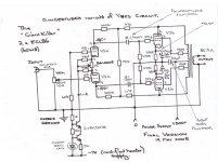
I have enclosed a copy of heathkit schematic that all the transfomers were pulled from.
Have aslo attached new schematic that I used to build this amp.
The PSU is CRC using 50uf + 100uf and a dropper of approx 330R.
I notice the heathkit schematic does not use a bleed resistor, however it powers a preamp section that I don't use. And considering it also uses 4 ecl86 in PP - I always thought it would be able to handle the power.
The beeld resistor has always been extremley hot, so have the output caps as they are soldered directly to pin 9 of the ecl86.
I remember that the old heathkit developed a fault that caused the amp to bubble and wax dripped from the power transformer onto the chassis. I thought the transformer was dead until someone from this forum persuaded me that it may not be. So when I built the new amp I tested the transformer unloaded and it seemed to work. Although I only tested it for a few seconds to see if I had secondary/heater currents etc.
I have enclosed a copy of heathkit schematic that all the transfomers were pulled from.
Have aslo attached new schematic that I used to build this amp.
The PSU is CRC using 50uf + 100uf and a dropper of approx 330R.
I notice the heathkit schematic does not use a bleed resistor, however it powers a preamp section that I don't use. And considering it also uses 4 ecl86 in PP - I always thought it would be able to handle the power.
Attachments
I don't think its a power limitation in the transformer. As you say, the original design has more valves and has similar operating currents. If the transformer has in the past suffered some internal damage, then it should be possible to establish what.
Another thing to check - are you able (very carefully) to measure the two AC voltages on the HT leads relative to the centre tap? Try this with and without the rectifier valve fitted. They should both pretty much the same, but can be quite a bit higher without the rectifier. If they are much different, that can point to an internal short in the HT windings.
Also, can you check the heater voltages for both channels? Heaters my glow, but again there could be a partial short resulting in an unexpected difference.
As 12E1 says, I think it is oscillating. Can you post a pic of your build? Have you got the UL taps on the output transformer round the right way? I guess you have not swapped the driver LTP anode connections as they are ECL86.
Cheers Matt.
Cheers Matt.
Polypropylene caps are large and ECL86 triodes have high anode impedance, so you have to be careful not to create an HF oscillator from stray capacitive feedback. Both signal phases are present so it doesn't take much for some positive feedback to appear.
@surfstu...
As mentioned before, if you are able to post a photo or two showing the wiring detail, it may help with checking and analysis.
As mentioned before, if you are able to post a photo or two showing the wiring detail, it may help with checking and analysis.
Does the transformer heat up with no tubes in the amp? Try it just without the rectifier tube too.
re post8,
It was a clever and very practical idea to use sockets to fit the majority of tubes/valves.
Why do we use so few sockets for transistors?
It was a clever and very practical idea to use sockets to fit the majority of tubes/valves.
Why do we use so few sockets for transistors?
Last edited:
I thought transistors were suppose to last forever? Why socket it if so. Provided of course that DIYer's like me learn how to keep the magic smoke from leaking out.
I think it would be justified to snip a wire and take a current measurement.
There is a rational explanation for everything. You just have to go find it.
There is a rational explanation for everything. You just have to go find it.
Thanks everyone, I will run the amp without tubes for a while and see how the transformer copes - I have to admit I am slightly scared of switching it on again but the mains plug is fused and there is an internal 2A fuse between the live from the IEC socket and the primary winding.
Where would be the best diagnostic place to put an ammeter? Would it be after the final smoothing cap? i.e. cut the smoothed HT wire before it goes to OPT's and insert DVM in series?
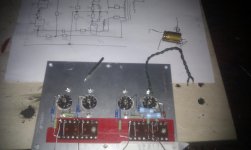
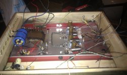
I have posted some shots, I know some will call me insane to have built a 'high rise block' of components around the valve sockets and I have to admit that half way through piecing together the jigsaw of components I thought I had gone insane too. Sometime the simplest schemtaics can become quite complex when you get the soldering iron out! Anyway I checked and double checket for shorts around the valve sockets but I will check again when I get home.
If I have 300 Volts being bled by a 30K resistor, does this mean I am draining 10mA to ground?
and... what is the worst that can happen if I power up the amp? If the transformer is doomed do I need to take any further precautions?
stuart
Where would be the best diagnostic place to put an ammeter? Would it be after the final smoothing cap? i.e. cut the smoothed HT wire before it goes to OPT's and insert DVM in series?
I have posted some shots, I know some will call me insane to have built a 'high rise block' of components around the valve sockets and I have to admit that half way through piecing together the jigsaw of components I thought I had gone insane too. Sometime the simplest schemtaics can become quite complex when you get the soldering iron out! Anyway I checked and double checket for shorts around the valve sockets but I will check again when I get home.
If I have 300 Volts being bled by a 30K resistor, does this mean I am draining 10mA to ground?
and... what is the worst that can happen if I power up the amp? If the transformer is doomed do I need to take any further precautions?
stuart

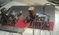
Is that tape under the paxolin tag boards? They really should be raised up off the chassis.
Cheers Matt.
Cheers Matt.
The way the tag boards are mounted, they will easily create a short to the chassis - which has probably already happened...
Besides, those higher wattage resistors will fry the capacitors that are touching them. Not a good idea IMHO.
Rundmaus
Besides, those higher wattage resistors will fry the capacitors that are touching them. Not a good idea IMHO.
Rundmaus
S**t
If only you knew how long I had spent.... I even discovered I was at an age that I needed glasses whilst soldering that lot together! I did think it may not be such a good idea to place all the components so close to the pins but I remember thinking that some components were better placed as close to the valve socket as possible and I had seen many DIYer pics on this site showing all sorts of configs are the valve sockets.
As for the red tape below the tag boards - I thought a couple of layers of electrical tape would be suffice to insulate it from the chassis. However, now I know how hot the whole thing can get - I am beginning to realise my stupidity.
I don't beleive that the high wattage resistors are necessary, it is all they had at the parts shop where I purchased most of the components, however, I am going to start again with better spacing of the components and lifting the tag board with spacers. Could anyone tell me which components in this simple circuit are suited best to move away from the valve sockets and then use interconnect wires to join them?
This way I can rule out the possibility of too much current being drawn by a possible short / breakdown of the red tape etc.
I am still very concerned about the fact that this power transformer has suffered two bubbling / boiling events now in its life (that I know of).
As one of the posters recommended - I removed all valves tonight and powered up. I measured the unloaded value of center tap to one anode at 296V and the other at 295V which seemed OK. I ran it for half hour and no heat appeared in the transformer. I then inserted the rectifier back in and got 390V DC and still the transformer did not get hot. I then inserted two ecl86's and ran one channel - sweet music and some warmth. Then I ran it normally with both channels / all valves and it worked but one channel is now very quiet and the heat is back. Could one of the capaitors already have dried out? They were running very hot over the last month.
Could the transformer now have permenent damage due to boiling a couple of times?
All answers on a postcard please (seriously I really appreciate all the comments so far, without you guys this amp would not have been built, and it sounds incredible when working)
Stuart
I'd start by trying to get those terminal boards elevated a bit off the chassis. It appears from your photos that they were installed on the tape and that some of the connections were soldered afterwards - please correct me if I'm wrong. If this is the case, the tape could have been compromised by the heat conducted by the terminals as you soldered them. For a quick-and-dirty test, I'd loosen the hardware holding the terminal boards to the chassis and slip something insulating (thin plastic sheet, perhaps?) into the space to separate them from ground and try the amp again.
Good luck.
-Pat
Good luck.
-Pat
So you know that it "can" work. Good. The problem is likely that something gets hot, probably there is a short circuit through the tape which appears when things are hot but not when they're cold. Although even when cold you really need to have some distance between things. The tape can perforate under pressure as well as when hot.
Good that you made the measurements. The AC voltages sound fine and so was the off-load DC voltage - so I would repeat the measurement with all of the valves removed just once more. So long as the voltages are still there (I suspect they will be) and so long as there is no major heating over an hour or two running in that state, then the transformer is almost certainly still OK.
I would advise that you should not be tempted to run it with all of the valves in again - you only increase the risk of something breaking.
Then pull it apart and prepare for the rebuild.
You should be able to tell by the sound the transformer makes when it is in an overloaded condition so you should not have to wait for it to heat up to know something is wrong. Make sure to listen to it each time you change something and it should become "clear" so to speak.
Thanks guys, am gonna get some plastic between the tag board and the chassis. And move the POI coupling capaitors (0.1uf) away from the sockets as these seem to have got too hot to touch too when the amp was running.
I always thought that point to point wirring meant getting as close to the valve sockets as possible....
stu
I always thought that point to point wirring meant getting as close to the valve sockets as possible....
stu
- Status
- Not open for further replies.
- Home
- Amplifiers
- Tubes / Valves
- Transformer bubbling