And you can kill a champion racehorse just by stroking him 😱I don't trust your models. You can lead a horse to water...🙄
'My' models are mostly Bob's as they are the most likely to have been tested in 'real life'. I'm quite particular in tracing their genealogy if you care to look in ricardo.txt
In most cases, Bob's models give the worst results for THD etc.
If you would care to tell us something about how you have validated your models, I'm sure we would all be grateful.
As to the circuits, as I explained in the original posts, I try not to deviate too far from my Jurassic experiments but SPICE models for the BJTs are Unobtainium so I've used the closest that appear validated.
________________
Michael, it would add substance to your claims if you would post a simple 'real life' circuit that incorporates your ideas and has good performance. 🙂
Much better than mucking up someone else's circuit/model & then taking pot shots at the travesty. 🙄
You may note that I've taken the most time & trouble with people who have posted 'real life' circuits & measurements.
This is cos I started my naive attempts at LTspice this year to see if it could sim some of the 'real life' stuff I observed in Jurassic times. I'm reluctant to waste time on purely theoretical flights of fancy. 😀
I'm pretty impressed with LTspice .. not cos the 'linear' stuff that you love ... that I used to do with my own circuit analysis programme circa 1980 .. but cos the non-linear stuff eg instability on only part of the waveform .. where LTspice sims are remarkably close to 'real life' with good models.
Last edited:
Stuff on VAS output?
___________________
Damir, was this in the sim or 'real life'?Keantoken, without RC's at the VAS output it's got berserk.
___________________
keantoken said:You can try 47R+220p RCs across the output BCs as shown in Cordell's book.
Just a reminder that stuff on the output of the VAS and stuff on the drivers & outputs do different things. I think both are evil but that's another topic.I tried that too, but with 220pF, 47pF is not enough. Electrically that is the same as connection from bases to the ground and LTspice shows exactly the same result, but probably in real PCB it is better solution.
P.S. I used predrivers across BCs connected 220pF ceramic cap, in my TT amp, and that tamed triple OPS.
- stuff on the VAS output will appear in your .ASC Inner & Main Loop Gain plots, Tian etc.
- stuff AT the terminals of Driver or Outputs deal with 'parasitic' stuff and the effects are probably NOT shown by your SPICE model. Cherry has them directly at the pins of the devices on the Heatsink
Last edited:
Damir, was this in the sim or 'real life'?
Just simulation, never tried pure Cherry in real life.
___________________
Just a reminder that stuff on the output of the VAS and stuff on the drivers & outputs do different things. I think both are evil but that's another topic.
- stuff on the VAS output will appear in your .ASC Inner & Main Loop Gain plots, Tian etc.
- stuff AT the terminals of Driver or Outputs deal with 'parasitic' stuff and the effects are probably NOT shown by your SPICE model. Cherry has them directly at the pins of the devices on the Heatsink
My mistake, I used B-C connected 220pF on drivers not predrivers in my triple TT amp, means no load to the VAS, and that was in real life. For pure Cherry implementation into Little GEM any compensation after drivers(EF2 OPS) did not help(in simulation).
BR Damir
Last edited:
I have made some very uncluttering trace parasitic symbols you can use in your schematics without cluttering everything up. It is easy to insert in series with the base of a transistor or anywhere really. It does not display text on the schematic, you must right-click it to set parameters.
Unzip the symbols into your schematic directory or even add them to your /lib/sym directory.
Now we will be a bit more encouraged to add parasitic inductances. 😉
Unzip the symbols into your schematic directory or even add them to your /lib/sym directory.
Now we will be a bit more encouraged to add parasitic inductances. 😉
Attachments
Damir's Little GEM from #210
My analysis of the Little Gem, Cherry version, that Damir posted in #210. LittleGEMpureCherry.ASC is his circuit as is.
It appears to be necessary to have C2 330p, the input roll-off, always connected. This is in line with ‘real life’ for amps with zillion MHz bandwidth.
There is a 50-55MHz glitch which comes & goes with each invocation of LTspice. It’s easy to see it in the Bode plots & ignore it but it appears in .TRANS too. In fact it appears on all types of compensation and even no compensation at all !
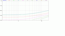
GEMcherryTHD.gif & GEMcherry20k.gif show the good distortion performance … 2-3 ppm at 20kHz for 50W 8R. The 20k residual plots show 2 cycles of 20kHz at a level of 0.01%
My analysis of the Little Gem, Cherry version, that Damir posted in #210. LittleGEMpureCherry.ASC is his circuit as is.
It appears to be necessary to have C2 330p, the input roll-off, always connected. This is in line with ‘real life’ for amps with zillion MHz bandwidth.
There is a 50-55MHz glitch which comes & goes with each invocation of LTspice. It’s easy to see it in the Bode plots & ignore it but it appears in .TRANS too. In fact it appears on all types of compensation and even no compensation at all !
GEMcherryTHD.gif & GEMcherry20k.gif show the good distortion performance … 2-3 ppm at 20kHz for 50W 8R. The 20k residual plots show 2 cycles of 20kHz at a level of 0.01%
Attachments
Mods to Damir's Little GEM
GEMcherry.ASC shows my mods.
It’s likely the only difference between the 2 versions to be seen in ‘real life’ would be slightly better THD20k, particularly a less spiky residual. Layout, decoupling & grounding have to be 1st class to see even this.
Both the ‘Inner’ Loop Gain with the Tian probe on base of Q7, the VAS i/p … and the ‘Main’ Loop Gain at base of Q2, the –ve i/p, are good for both versions with exotic loads. Closed Loop response drops nicely monotonically except for the 50-55MHz glitch.
The original is –3dB @ 1MHz with my modified version, at 400kHz.
The ‘non-linear’ stability tools with .TRANS give both a clean bill of health.
I’ve also
A more important change, which again has little effect on THD, stability or overload behaviour is replacing MOSFET M1, R20 & R25 with a 2k resistor. This is in keeping with my Muntz philosophy.
GEMcherry.ASC shows my mods.
- Remove R30/31 C8/19, decoupling the bases of the Drivers to earth.
- C13, the Cherry cap, becomes 47p
- R8/10 becomes 47 to restore LG for the main loop
- add C22 220p, decoupling the VAS emitter resistor
It’s likely the only difference between the 2 versions to be seen in ‘real life’ would be slightly better THD20k, particularly a less spiky residual. Layout, decoupling & grounding have to be 1st class to see even this.
Both the ‘Inner’ Loop Gain with the Tian probe on base of Q7, the VAS i/p … and the ‘Main’ Loop Gain at base of Q2, the –ve i/p, are good for both versions with exotic loads. Closed Loop response drops nicely monotonically except for the 50-55MHz glitch.
The original is –3dB @ 1MHz with my modified version, at 400kHz.
The ‘non-linear’ stability tools with .TRANS give both a clean bill of health.
I’ve also
- moved R18/26 to the output bases
- reduced C10 & removed C16
- increased R15/16 to 270 on the CM
A more important change, which again has little effect on THD, stability or overload behaviour is replacing MOSFET M1, R20 & R25 with a 2k resistor. This is in keeping with my Muntz philosophy.
Attachments
If the circuit is unstable without it, you can use C2 to bypass R1 in simulation and that will allow you to inspect full BW behavior. This is provided your AC source has impedance not much higher than the cap.
kgrlee, I like the aim of your work. I built 5 amplifiers after simulating them, all using ANYTHING but miller compensation. I don't claim this was rational for me, but you have no rational thoughts about ANY subject until you have learned about it. After enough bungee jumping and hang gliding, I decided I knew a lot of useful things about compensation and decided to try and aim for a more difficult goal - phase linearity, safe overload and unconditional stability. An amplifier can be stable without being phase-linear, but if you can make an amp phase-linear at all operating points it is a good indication of rock solid stability. I'm not saying you don't strive for these things already, I just want you to try adding phase linearity to the list.
I want to see what you can do by paying attention to the group delay plot in AC analysis, to make it smooth across as large a range of output currents and voltages as you can, while maintaining your focus on distortion performance. For me this exercise has improved my focus, because of having to take into account a new set of mechanisms, and it has made me better at what I already know.
I had the impression that the Goldmund amp was designed for phase linearity, even if it is not regarded as a sane design my many gurus (that was my impression anyway). I think you'll find that the simplest designs are the easiest to achieve phase linearity with. Multi-pole compensations endlessly frustrate phase-linearity, though TMC is very benign. Getting a "highly compensated" amp phase linear is a great challenge.
Wow. I really like that phrase, "highly compensated". I think I will be using that description a lot.
'My' models are mostly Bob's as they are the most likely to have been tested in 'real life'.
Do you know this for a fact? 🙄
The ZTX1056A/796A are relatively slow with their 500p/220p Cbe. This is completely different from using something like the 2SC3501/A1381.
How about at least using models you trust that are remotely similar to the devices we're actually using?
The problem is I don't trust your models. ZTX1056A/796A models correlate rather well with performance of the practical devices.
models & a challenge
Bob has chapters in his book on this.
____________________
Now here's a challenge Michael. How about you post one of YOUR circuits with YOUR pet theories & models?
I may
You are of course welcome to do the same with any of MY models that I have posted. Note that some of these models are part of an illustrative series. So on page 1 of this thread, the model to beat isn't #1 or #2 which are my poor attempts at your TPC/TMC methods .. but #4 which is 'pure Cherry'.
If you tell me which one you want to try, I can tell you how close it is to something which I've done in 'real life' Jurassic times.
Remember, the challenge is to improve on the other fellows work .. not to muck it up. We already know you can do the later. 😀
Michael, if you can tell us how you have validated your models, I'm sure we will all be grateful 🙂The problem is I don't trust your models. ZTX1056A/796A models correlate rather well with performance of the practical devices.
Bob has chapters in his book on this.
____________________
Now here's a challenge Michael. How about you post one of YOUR circuits with YOUR pet theories & models?
- preferably a 'real life' example but SPICE world will do
- but it has to be complete. ie no 'ideal' current sources, VCCS etc
- everything done with YOUR dodgy .. I mean validated against datasheet & 'real life' ... models
- with what YOU consider good performance & stability.
- And please have sensible bits on the output like Zobels & output L etc .. You can leave them out if you consider instability under various loads acceptable.
I may
- only use YOUR models
- simplify YOUR topology or use a simpler one if your favourite topology is 2 difikult 4 mi smal bren 2 unerstan 😱
- only add (YOUR) devices if I remove at least a similar number of active devices elsewhere
You are of course welcome to do the same with any of MY models that I have posted. Note that some of these models are part of an illustrative series. So on page 1 of this thread, the model to beat isn't #1 or #2 which are my poor attempts at your TPC/TMC methods .. but #4 which is 'pure Cherry'.
If you tell me which one you want to try, I can tell you how close it is to something which I've done in 'real life' Jurassic times.
Remember, the challenge is to improve on the other fellows work .. not to muck it up. We already know you can do the later. 😀
Last edited:
Thanks for your kind comments Kean.... After enough bungee jumping and hang gliding, I decided I knew a lot of useful things about compensation and decided to try and aim for a more difficult goal - phase linearity, safe overload and unconditional stability. An amplifier can be stable without being phase-linear, but if you can make an amp phase-linear at all operating points it is a good indication of rock solid stability. I'm not saying you don't strive for these things already, I just want you to try adding phase linearity to the list.
I wrote about 'phase linearity' in 1981 (actually 1978) Is Linear Phase Worthwhile? and am somewhat surprised that there's nothing I would change in its conclusions 3+ decades on ... after being a beach bum for more than a decade.
I'm really a speaker man and regard the amp as just another xover component. Stability & overload behaviour is big on my list cos these are things which are readily discerned in Double Blind Listening Tests bla bla.
1ppm THD20k is a fun exercise for me but ONLY if it doesn't involve ANY extra complexity or compromise other stuff like overload & stability. Even going from single VAS to the Blameless enhanced VAS is something I constantly look at with a jaundiced eye.
That's why I'm not really interested in fancy topologies cos hardly any of them achieve 1ppm THD20k ... which I can already do with my simple Jurassic circuit ... using even Bob's poorest output devices.
It takes ALOT of time & 'real life' testing to be confident in a new topology. I try not to recommend anything which I haven't at least vaguely tried in 'real life'.
You are probably right about 'phase linearity' giving better stability in the various loops but I don't think it says anything more than older recommendations like Bode.
My naive designs, with their extreme simplicity, have only a few dodges to fudge stability. So it's important to use them as effectively as possible .. without introducing evils like compromising my heretical HiZ VAS output. 😱
Just found out that what I call a Nyquist kink ... is da pedant's 'Bode Step'.
You have demonstrated in simulation you can meet your expectations for "unconditional" stability. I agree that phase linearity isn't necessary for unconditional stability. It is however the "icing on the cake" to get no ringing whatsoever caused by the amp itself.
Phase nonlinearity shows up as peaks in the group delay. A peak in the group delay means energy is being stored. Stored energy is bad for overload behavior. They also correspond to resonances in the amplifier which may interact with RFI.
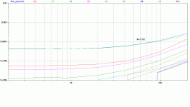
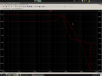
Consider the attached plot. The AC corner looks sharp and geometrical; it seems everyone likes to see this kind of curve. But when you look at the group delay it's clear the corner is artificially sharpened by an underdamped resonance. This amp will most likely show overshoot on the step response even though the AC response is smooth. Without understanding this relationship, designers will struggle to find an explanation and will fault the topology, the components, the parasitics, and so on, but not fault their implementation thereof.
In power amps, this might be seen as a non-issue. In gain blocks however which are used in larger loops, the phase nonlinearity and energy storage can build up or be multiplied and cause real issues. So at the very least it's worth being aware of.
Phase nonlinearity shows up as peaks in the group delay. A peak in the group delay means energy is being stored. Stored energy is bad for overload behavior. They also correspond to resonances in the amplifier which may interact with RFI.
Consider the attached plot. The AC corner looks sharp and geometrical; it seems everyone likes to see this kind of curve. But when you look at the group delay it's clear the corner is artificially sharpened by an underdamped resonance. This amp will most likely show overshoot on the step response even though the AC response is smooth. Without understanding this relationship, designers will struggle to find an explanation and will fault the topology, the components, the parasitics, and so on, but not fault their implementation thereof.
In power amps, this might be seen as a non-issue. In gain blocks however which are used in larger loops, the phase nonlinearity and energy storage can build up or be multiplied and cause real issues. So at the very least it's worth being aware of.
Attachments
Don't want to stray too much on your turf, Richard, but I was just curious how well your ideas worked. I had a look at the original version of your Cherry ideas at the beginning of the thread, and am seeing some instability creeping in when the load drops to 2R or more. Am I missing something here, and/or have you updated the schematic?
Thanks,
Thanks,
Frank, how are you assessing stability?Don't want to stray too much on your turf, Richard, but I was just curious how well your ideas worked. I had a look at the original version of your Cherry ideas at the beginning of the thread, and am seeing some instability creeping in when the load drops to 2R or more. Am I missing something here, and/or have you updated the schematic?
You might want to try the post #56 version instead of the 1ppm 50W 20kHz #4 version. It's got 10dB better margins all round if you're worried about stability.
That's the one (or something close) I would probably build in real life as beach bums have problems measuring 1ppm THD in Cooktown.
The #56 version only has 2ppm THD for 50W 20kHz 8R in SPICE world. I'm sorry I made such a botch of it. 😡
Won't be able to do any serious work on this or other stuff for more than a month but please post what you find.
Quick answer: at 2R load with the source as per #4, high frequency oscillation is starting to appear in the output waveform, after the Zobel, at the point following the negative peak. Prior to the Zobel it's much worse ...
Cheers,
Cheers,
Last edited:
- Home
- Amplifiers
- Solid State
- TPC vs TMC vs 'pure Cherry'