I have a proposition:
Offering a D amplifier with basic current feedback as proposed by Esa Merilainen would make a product unique on the market.
For fullrange loudspeakers this amp topology has its benefits - mainly a reduction of distortion by 10 to 20 db(!)
Offering a D amplifier with basic current feedback as proposed by Esa Merilainen would make a product unique on the market.
For fullrange loudspeakers this amp topology has its benefits - mainly a reduction of distortion by 10 to 20 db(!)
Hello 3eAudio 🙂
Before expressing myself, I hope that you do not take my remarks badly, it is not the goal but rather to be 'constructive'.
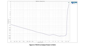
As usual, you are certainly very friendly BUT: your THD+N curve as it stands means absolutely nothing... 👈
You don't even specify the load used (I think it's 4 Ohms) and you don't even specify which of your PCBs it is 😒
In the introduction, you talk about: "...a custom version with most circuits/parts upgraded..." without any further clarification... 🙁
In conclusion, your post presents a superb curve but it is completely useless if you do not provide more details 😢
I believe in my humble opinion that most readers expect something else from you as this is completely incomparable with the very excellent quality of your PCBs 😎
Make a little effort please because in addition you will see that 'it pays' 😉
Cordially.
Before expressing myself, I hope that you do not take my remarks badly, it is not the goal but rather to be 'constructive'.
As usual, you are certainly very friendly BUT: your THD+N curve as it stands means absolutely nothing... 👈
You don't even specify the load used (I think it's 4 Ohms) and you don't even specify which of your PCBs it is 😒
In the introduction, you talk about: "...a custom version with most circuits/parts upgraded..." without any further clarification... 🙁
In conclusion, your post presents a superb curve but it is completely useless if you do not provide more details 😢
I believe in my humble opinion that most readers expect something else from you as this is completely incomparable with the very excellent quality of your PCBs 😎
Make a little effort please because in addition you will see that 'it pays' 😉
Cordially.
These are not the same scales: take a good look -> the abscissas are at 300W on the first curve and at 200W on the second.
Moreover, this axis has been 'tinkered': this is what I see clearly...
By doing this, it 'packs' the curves and they look better, this is well known and very commonly used by builders.
Moreover, this axis has been 'tinkered': this is what I see clearly...
By doing this, it 'packs' the curves and they look better, this is well known and very commonly used by builders.
look nice compare curve, can you tell me which tool can import this 2 curve into 1? thanks!
@muducu sorry that i didn't include not so much info on that, the purpose here is to show how the capability of the tpa3255 chip it can be done with optimized design, the new curve is 4ohm with 51V and the old one is 48V,test with same power supply (LOF550-20B48) mentioned above.
Good morning 3eAudio 😉
Everyone knows that the performance of the TPA3255 is even better the closer you get to its maximum operating voltage 👈
You will have nevertheless provided some small details but they are not sufficient following what you said at the very beginning, I quote you again: "...a personalized version with most of the circuits/parts updated. .. "...
This sentence could even mislead future buyers of your PCB since it seems to say that modifications are to be expected on it to obtain a better result 🙄
In other threads posters claim tpa3255 works best (lowest thd) at 35V , I am sure you read those posts too, it is certainly not common knowledge in the tpa3255 threads on this website/among the diyconnaisseurs 🙂
People hi 
@TNT ->
You seem to have mastered your PHOTOSHOP software well:
in this case, now that you have put things 'in order' concerning the abscissa scales, can you superimpose the two curves that 3eAudio showed us (before and after) so that we can actually notice the differences announced following this 'upgrade', please
We could thus see the level of improvement obtained and become curious with them to find out more about the details of this upgrade, its implementation (difficult or not) and, of course, estimate its cost to consider possible on our amplifiers.
I think this is going to be really interesting... 🔍
@ irribeo ->
I am not aware of a link that allows to know more about your assertion concerning your assertion on the voltage of use of the TPA3255 at 35volts:
can you give us a link that can allow us to know more please
See you soon
Thats what it shows - the measurement from the product page and the improved one posted here.
-86 -> -100 dB
//
-86 -> -100 dB
//
Last edited:
I'm also curious about what improvements have been made. And whether they are applicable to the module of this amplifier purchased by me on Aliexpress.
@ TNT ->
where do you see this improvement ?
Unless I misunderstood you, the darkest curve on the graph indicates the results obtained with an 8 Ohm load, the other lighter curves are the results with a 4 Ohm load...
@ maciekw ->
No worries with the PCB from ALIEXPRESS, it's almost perfect, I received one a week ago (not tested yet as I'm waiting for my new power supply 😢 ).
-> I will present 'here' my amplifier equipped with this PCB as soon as it is fully finished, I think towards the end of the month 😎
In conclusion, the only regret is the use of OPA1612 OPAMPS which are also soldered on the PCB without the possibility of adding others... 👈
Indeed, although this OPAMP has interesting characteristics in terms of THD (0.000015%), I find for my part that it is far from being the most musical (it cannot be measured, we have not yet invented device for this).
My preference is for the OPAMP OPA 828 which uses FET technology, the OPA 1612 being a BIPOLAR.
On this subject 3eAudio does not communicate, they just point out that replacing this OPAMP would 'disrupt' the rendering in terms of sound quality... 🙄
I'm not sure because I don't have the input circuit diagram (yet) but just considering the fact that the PCB input impedance is 10K (unbalanced) and 20K (balanced), the OPAMP used is not at all the most suitable since its THD increases sharply from about 3K whereas an OPAMP in FET technology (like the OPA 828) from this value is no longer dependent on that -this is its THD will be at the maximum that of the resistance at the input of the circuit.
Here is an illustration chart from TEXAS INSTRUMENTS for better understanding ->
.jpg")
We can see very clearly on this example that in this case, the THD of the bipolar OPAMP is much more important than with the OPAMP FET at 10K and even more at 20K: it's not me who says it is the manufacturer (TEXAS INSTRUMENTS) of these OPAMPS 👈
This last AOP (828) has also been studied to show only a maximum of even harmonics while reducing the most the odd harmonics which are all below the level of the even harmonics, which generally makes listening much more pleasant for listeners 😀
The choice of the OPAMP OPA 1612 is not the best either since the OPA 2211 (available in double mounting on DIP8 adapter because it's a single SOIC8 OPAMP) is more efficient in terms of bandwidth, open loop gain and offset voltage at its inputs but it would have been necessary to be able to replace the OPAMPS, which is not the case on this PCB since it does not offer the possibility of OPA ROLLING since the PCB is not equipped with a DIP8 'tulip' support 🙁
Otherwise and for simplicity, I invite 3eAudio to carry out tests with double OPAMPS in FET technology in SOIC8 format so as not to modify the PCB, namely:
- OPA 1642: 'neutral' tone
-OPA 1656: 'dynamic' tone but a slight 'rising' tendency in the treble.
Measurements in terms of PCB noise with these OPAMPS could confirm or invalidate my comments if 3eAudio is 'ready' for this exercise which could be very interesting 😉
Cordially.
where do you see this improvement ?
Unless I misunderstood you, the darkest curve on the graph indicates the results obtained with an 8 Ohm load, the other lighter curves are the results with a 4 Ohm load...
@ maciekw ->
No worries with the PCB from ALIEXPRESS, it's almost perfect, I received one a week ago (not tested yet as I'm waiting for my new power supply 😢 ).
-> I will present 'here' my amplifier equipped with this PCB as soon as it is fully finished, I think towards the end of the month 😎
In conclusion, the only regret is the use of OPA1612 OPAMPS which are also soldered on the PCB without the possibility of adding others... 👈
Indeed, although this OPAMP has interesting characteristics in terms of THD (0.000015%), I find for my part that it is far from being the most musical (it cannot be measured, we have not yet invented device for this).
My preference is for the OPAMP OPA 828 which uses FET technology, the OPA 1612 being a BIPOLAR.
On this subject 3eAudio does not communicate, they just point out that replacing this OPAMP would 'disrupt' the rendering in terms of sound quality... 🙄
I'm not sure because I don't have the input circuit diagram (yet) but just considering the fact that the PCB input impedance is 10K (unbalanced) and 20K (balanced), the OPAMP used is not at all the most suitable since its THD increases sharply from about 3K whereas an OPAMP in FET technology (like the OPA 828) from this value is no longer dependent on that -this is its THD will be at the maximum that of the resistance at the input of the circuit.
Here is an illustration chart from TEXAS INSTRUMENTS for better understanding ->
We can see very clearly on this example that in this case, the THD of the bipolar OPAMP is much more important than with the OPAMP FET at 10K and even more at 20K: it's not me who says it is the manufacturer (TEXAS INSTRUMENTS) of these OPAMPS 👈
This last AOP (828) has also been studied to show only a maximum of even harmonics while reducing the most the odd harmonics which are all below the level of the even harmonics, which generally makes listening much more pleasant for listeners 😀
The choice of the OPAMP OPA 1612 is not the best either since the OPA 2211 (available in double mounting on DIP8 adapter because it's a single SOIC8 OPAMP) is more efficient in terms of bandwidth, open loop gain and offset voltage at its inputs but it would have been necessary to be able to replace the OPAMPS, which is not the case on this PCB since it does not offer the possibility of OPA ROLLING since the PCB is not equipped with a DIP8 'tulip' support 🙁
Otherwise and for simplicity, I invite 3eAudio to carry out tests with double OPAMPS in FET technology in SOIC8 format so as not to modify the PCB, namely:
- OPA 1642: 'neutral' tone
-OPA 1656: 'dynamic' tone but a slight 'rising' tendency in the treble.
Measurements in terms of PCB noise with these OPAMPS could confirm or invalidate my comments if 3eAudio is 'ready' for this exercise which could be very interesting 😉
Cordially.
Last edited:
The "red" trace are from the improved version. The dark are for the ones sold on Aliexpress. The improved ones have 12 dB lower distortion up to 2 watts, then it gets less and at 33 watt is actually worse but improves agin. The improved version seem to offer quite a lot more power - 210 vs 125 w - say 2 dB more. In order to achieve that a higher voltage power unit must have been used.
In a really good system, less distortion is always an improvement as I see/hear it. opa rollers are twiddlers 🙂
//
In a really good system, less distortion is always an improvement as I see/hear it. opa rollers are twiddlers 🙂
//
@ TNT ->
You don't understand 🙁
Read what I wrote carefully: the black curve is that for a load (of the speakers) of 8 Ohms and the clearest is that for a load of 4 Ohms.
Do not confuse everything
Also, the frequency response will be different depending on the load.
This directly depends on the circuit used at the output of the PCB (SELFS, FILM CAPACITOR and RESISTOR) which on this PCB is optimized for use with a 4 Ohms load.
We can also see an illustration of it on the manual of this PCB with a graph shown by 3eAudio ->

You understand better now ?
You don't understand 🙁
Read what I wrote carefully: the black curve is that for a load (of the speakers) of 8 Ohms and the clearest is that for a load of 4 Ohms.
Do not confuse everything
Also, the frequency response will be different depending on the load.
This directly depends on the circuit used at the output of the PCB (SELFS, FILM CAPACITOR and RESISTOR) which on this PCB is optimized for use with a 4 Ohms load.
We can also see an illustration of it on the manual of this PCB with a graph shown by 3eAudio ->
You understand better now ?
What are you on about - the ones I showed was for distortion - what you reshowing I have not idea. Sorry.
//
//
Here are the results of measurements of the module sold on Aliexpress under a 4 ohm load. And these results are worse than the results of the improved version of this amplifier. This can be easily read. And so the standard version has a distortion of more than 0.01% at 10mW, while the improved one at the same 4 ohm load has a distortion of about 0.006%. At 10 watts, the standard version has distortion of 0.0005% and the improved version has 0.0003%.
Attachments
- Home
- Vendor's Bazaar
- TPA3255, TPA3251 with Post Filter Feedback(PFFB)