Thanks, link just added. My writeup was done back in March 2023, before Tom's Stereophile review a couple months later.
Hi all, been lurking on this thread as I work on this as my first DIY build, just finished all of the SMD parts. But I had a couple questions.
1) For the solder/wire bridges, I know I need w191, w194, and from looking at the pic posted earlier, I also need w161, w151, w141, w111, and w101, correct? I don’t need to bridge w131?
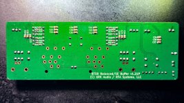
2) so for no PFFB 0ohm jumpers on the A,B,C,D?
3) currently waiting on a SMPS from Micro Audio, question I had was that I was planning on using the SFPP. Realized I probably don’t want to instal that before the SMPS, as I want the always on going to the buffer, correct? So can I install it after the SMPS? Or do I need a different soft start module?
4) last question, wanted to confirm 2.5a for the mains fuse—based in the US so 120v.
Thank you! Really enjoying this build so far!
1) For the solder/wire bridges, I know I need w191, w194, and from looking at the pic posted earlier, I also need w161, w151, w141, w111, and w101, correct? I don’t need to bridge w131?
2) so for no PFFB 0ohm jumpers on the A,B,C,D?
3) currently waiting on a SMPS from Micro Audio, question I had was that I was planning on using the SFPP. Realized I probably don’t want to instal that before the SMPS, as I want the always on going to the buffer, correct? So can I install it after the SMPS? Or do I need a different soft start module?
4) last question, wanted to confirm 2.5a for the mains fuse—based in the US so 120v.
Thank you! Really enjoying this build so far!
Attachments

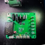


I’ll have to look at all the jumpers but all the ones on top side need jumpers so W131 yes. The bottom side selects mode of operation so go with diagram I provided.
No soft start needed. That’s only needed for linear trafo PSU. SMPS don’t have huge in rush current. The on/off low voltage switch is provided by the PSU connections.
The fuse is VA rating. Let’s aim for 10A to speakers, 52v peak is 18.4v rms x 10 A should equal fuse amps x 120vac. For stereo I get 3.15A. To give margin I would use 5A.
Use 0ohm jumpers for no PFFB on A/B/C/D.
Nice work with the soldering!
Wonderful, thank you! For the 0ohm jumper for A/B/C/D they’re 1/8w correct? Looking at these
Vishay / Beyschlag MCU08050Z0000ZP500
Vishay / Beyschlag MCU08050Z0000ZP500
That should work. There is no current in them so 1/8th W is fine. You could even use bits of wire or a solder blob.
Actually just realized my board doesn’t have A, B, C, and D. 😅
So now just gotta wait on a couple caps, and the SMPS to power it up!

So now just gotta wait on a couple caps, and the SMPS to power it up!
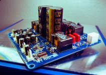
I would go over the solder joints on the legs of the TPA3255 chip with a hot iron and liquid flux on copper braid to clean up excess solder. You may have bridged joints. Also the solder looks crusty and not glossy smooth like the temp wasn’t hot enough. Reflow it with a hot chisel tip. Same with red boxed areas on the chip capacitors etc. especially the bootstrap ones on the output side. Those get a lot of voltage stress. Your chip looks a little shifted on bottom edge causing the diagonal shift.

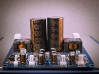
Here is what mine looks like with hot air topside and solder paste with frypan on bottom side. Frypan temp set to just below melt to provide preheat to the PCB.

I would recommend paste vs soldering iron for this. You can use an iron but be sure there are no bridged joints on the legs.
Here is what mine looks like with hot air topside and solder paste with frypan on bottom side. Frypan temp set to just below melt to provide preheat to the PCB.
I would recommend paste vs soldering iron for this. You can use an iron but be sure there are no bridged joints on the legs.
Last edited:
It’s ok if the two center pins are bridged since they go to the same ground.
But just need to wipe it with solder wick. Those TPA3255 pin pads look like they may be damaged or peeled off? Be careful cleaning them with solder wick.
But just need to wipe it with solder wick. Those TPA3255 pin pads look like they may be damaged or peeled off? Be careful cleaning them with solder wick.
@Omegaconjecture Looking good!! This design has strong recommendation even for some its as good as Class -AB designs.
Looking good! If the two LEDs showing 3.5v and 12v light up and you did everything else correct it should work. Check DIP switch settings for correct configuration. I assume you are doing stereo BTL?
Thank you! Think I got it! Finished the main board, SMPS comes in next week, so I guess we’ll find out then! Can’t wait!
Looks beefy for such a small board!
I assume this is the LSA GAN 350 ? Any plans to make it available for DIY ?I will also be developing a hybrid tube buffer Class D amp with 350wpc for a client as a commercial amp. Still early stages.
The 350w hybrid amp is no longer in the plan. If I make another hybrid it would be the TPA3255 with the HyperSET tube buffer combo.
The TPA3255 has an option for parallel bridge tied load (PBTL) mode. It allows double the current but voltage swing is the same. So to get more power, you need lower impedance speakers (2ohm). To get more power with same 8ohms, you need more voltage. Max voltage is 52v supply and so for BTL balanced output we get 104vpp or 36.7vrms. This means about 150w max at 8ohms, 300w at 4ohms. In PBTL it would be 600w at 2ohms. But that’s the absolute max with crazy 10% distortion. Practical power is closer to 125w at 8ohms.
Thanks X. Can the PCBs you are selling from your store be configured for PFFB ?
On the same theme, can a Warp 1 be modded in the same way?
On the same theme, can a Warp 1 be modded in the same way?
It depends on the board version. If you are interested in doing your own PFFB board I think I might have a few available.
Yes, the Warp-1 can be modified to have PFFB by changing 4 0R resistors to 3k6. These are the ones labeled A, B, C, D. 3 on the bottom and 1 on top. 0603 metal thin film SMD’s.
Yes, the Warp-1 can be modified to have PFFB by changing 4 0R resistors to 3k6. These are the ones labeled A, B, C, D. 3 on the bottom and 1 on top. 0603 metal thin film SMD’s.