Both the EVM datasheet and the TPA3255 DS specify 18V minimum supply, but seems they made an error on the EVM overview page where they state its 14V.
I have been wondering what is sacrificed when using voltages at the low end of the 18-53.5V range. Obviously total output W would be limited, but would it have any effect on the 112dB SNR or 0.006% THD+N?
If it does, I was thinking the tpa3245 which at the same specs takes 30V max with 115Wpc output (half the 3255!) may be a "greener" solution for high-efficiency speakers and offer the same sound quality.
If it does, I was thinking the tpa3245 which at the same specs takes 30V max with 115Wpc output (half the 3255!) may be a "greener" solution for high-efficiency speakers and offer the same sound quality.
A very good point. On paper several numbers for the TPA3245 are better - lower output noise, lower mid-power THD+N, better SNR. Better efficiency too as the output FETs have lower Rds(on).
Both the EVM datasheet and the TPA3255 DS specify 18V minimum supply, but seems they made an error on the EVM overview page where they state its 14V.
Question is, what does the buck converter (15V) when running in dropout mode. Also the following linear stage (12V) is running possible near dropout then. This might have an effect on PSRR for both buck and linear stage.
Edit: LM2940 dropout at 100mA load is only 110mV, so should be fine for the linear stage.
Last edited:
Yeah I was concerned about how many volts the LM5010 (buck) needed for full regulation, could not find it in the DS. The following regulator is an LDO (LM2940) so won't be close to dropout. Another concern of mine is the LM5010's output ripple is a couple hundred mV p-p at 600kHz but the LM2940 has no PSRR data beyond 1MHz.
Yes, the LM2940 is at ~110mV for 100mA load current. The bucks ripple must be taken into account as it is Vout-VripplePeak. So the maximum allowed ripple at 14V would the be 3.8Vpp for the bucks output -Which won't occur that high I'd guess.
Hi all
I build my amp TPA3255.
Input opamps full defferential THS4131, PSU MW LRS-350-48.
Very Nice!
This might answer a question I've had about this chip and EVM. As I see it, although this chip accepts differential inputs, there is no common mode noise reduction within the chip. The EVM buffers/inverts the hot/cold inputs and feeds them directly into the chip inputs. These signals are converted to PWM, amplified, and applied to one half of a BTL speaker.
If one wants noise removed from the balanced inputs, a chip like the THS4131 is needed ahead of the chip inputs, and the NE5532 op amps are not needed.
Is this correct?
Mike
Nope, balanced inputs usually don't have common mode noise. One just have to make sure, they're perfectly symmetrical. For less noise some additional feedback is needed to lower the fixed chipgain.
Last edited:
TPA325x are based on 4 single-ended amps. These SE-channels virtually do not provide any power supply rejection.
But configured as BTL, power supply noise is widely cancelled. You will find a PSRR-specification in the data sheet applicable for BTL only - something like 60dB. This number characterizes the symmetry between to legs of a full-bridge - not more. BTL as well as PBTL require a balanced input signal. This is what the OP-amps on the EVMs are good for.
But configured as BTL, power supply noise is widely cancelled. You will find a PSRR-specification in the data sheet applicable for BTL only - something like 60dB. This number characterizes the symmetry between to legs of a full-bridge - not more. BTL as well as PBTL require a balanced input signal. This is what the OP-amps on the EVMs are good for.
Last edited:
Thanks, that is exactly what I thought, except for the last sentence.
I'm new to op amps, but to me they are simple inverting buffers, and do nothing other than invert the signal. Well, in doing so the output signal is now riding on 6 volt dc instead of 0 volt dc, but the 10 uf cap will fix that before the signal enters the tpa325x chip. I think it also creates a low pass filter of around 756 kHz.
With single-ended inputs, the first part of the op amp inverts the signal from input se a and sends it through a 10uf cap to ina of the tpa325x chip. It also sends that inverted signal to the second part of the op amp, which inverts the signal again and sends it through a 10 uf cap to inb of the tpa325x chip.
If the circuit is already receiving differential signals on input se a and input se b, why not simply pass those signals straight to the 10 uf caps, bypassing the op amps?
My apologies for my ignorance. I'm probably way over my head, but interested.
Mike
You are welcome, no need for apologies.😉
I think you basically understand that op-amps circuitry. If you have a balanced signal source, there is indeed no need for all that stuff.
But if you have an unbalanced source, like the stereo headphone plug of your smartphone, you need to convert it to a balanced (stereo-) signal.
The op-amp circuit is universal in that it can accept balanced and unbalanced signals as well.
mhh, could you elaborate on that?An interesting idea, to use an additional integrator as in nCore.
I think he essentially means incorporating the buffer opamp as the front-end of a composite loop (using PFFB); not a huge bandwidth budget to work from, sadly, so the amount of extra loop gain you could introduce at 20 kHz would be pretty limited.
Someone can post pictures in good quality from top/bottom side with heatsink removed?
<snip>
Hi Doc
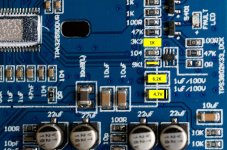
Here ist my blue chineese board without the heatsink with the yellow Mods
1. Replace the 1K0 Ohm resistor
2. Make a bridge over the 9K1 resistor
3. Replace the cap with the 6K2 resistor
4. Replace the cap with the 4V7 zener
5. Pray that you have made no mistake and that the doctor is right.
But there is no room for other components. Only the 6k2 and the 4V7 would go. the 9k1 bridge is verry difficult.
Is there another way to supress the on and off pop's.
Hans-Peter
Attachments
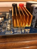
TPA3255 Chinese PCB - listening - modding...
Hi,
I just received from AliExpress, the Chinese version of the TPA3255 PCB. Currently I use the daily t-amp Sure 2X400w (Gremlin). after 2 days listening, and with different styles of music, jazz, classical, pop ... the sound are very clean and transparent.
On the other hand there is a very light ploc ignition, nothing too terrible. No noise when closed. I have 5 TPA311x PCBs and a TAS5613, and the TPA3255 is significantly superior to all points of view.
Finally I prefer it to t-amp Sure (I changed the input capacitors by Obbligato - Sure t-amp). I bought it from this seller.
AliExpress Mobile - Global Online Shopping for Apparel, Phones, Computers, Electronics, Fashion and more
Last edited:
That's also my question. I've changed from Gremlin to the chinese TPA3255 with a real good powersupply. The differences are:
The gremlin gets hotter without a heavy heatsink.
The gremlin has more 3d stage.
Are there so big differences between a chinese and a EVM Board?
Hans-Peter
The gremlin gets hotter without a heavy heatsink.
The gremlin has more 3d stage.
Are there so big differences between a chinese and a EVM Board?
Hans-Peter
@BIH,
9k1 has to be removed (that's what the red cross means).
The 6k2 needs to dissipate about 400mW at PVCC=55V, so i'd prefer the following:
Change the 6k2 for 100k (R6),
Change the 1k0 for 22k (R26)
9k1 has to be removed (that's what the red cross means).
The 6k2 needs to dissipate about 400mW at PVCC=55V, so i'd prefer the following:
Change the 6k2 for 100k (R6),
Change the 1k0 for 22k (R26)
- Home
- Amplifiers
- Class D
- TPA3255 - all about DIY, Discussion, Design etc