If one has speakers capable of reproducing 430kHz and ears sensitive at that frequency, one might hear some hiss? 🙂
Ok, I redid the cap feedback with 220pF 100v C0G 0603 at the input side.

Here is the test setup with qnty 2x fan cooled 10R 300W EBG non-inductive planar film resistors in parallel as dummy load for 5ohms nominal. Running about 22Vpp and the O-scope trace looks exactly the same with the load connected or disconnected. I should note that my amp is also implementing the standard TI PFFB circuit PLUS @bucks bunny cap feedback circuit.

And here is the O-scope trace:

I don’t know - does that look pretty good? There is still a little overshoot and maybe 4-5 cycles of highly damped damped ringing. Could it be that maybe 330pF is needed here?
I will do a listening test now.
Here is the test setup with qnty 2x fan cooled 10R 300W EBG non-inductive planar film resistors in parallel as dummy load for 5ohms nominal. Running about 22Vpp and the O-scope trace looks exactly the same with the load connected or disconnected. I should note that my amp is also implementing the standard TI PFFB circuit PLUS @bucks bunny cap feedback circuit.
And here is the O-scope trace:
I don’t know - does that look pretty good? There is still a little overshoot and maybe 4-5 cycles of highly damped damped ringing. Could it be that maybe 330pF is needed here?
I will do a listening test now.

Listening tests so far so good. Subjectively, the amp seems “smoother” and more relaxed yet still engaging and detailed. It might all be confirmation bias though. 😁
So if I understand you correctly, you are employing both the TI PFFB circuit and an extra cap from post filter to input?
If this is the TI PFFB circuit, aren't you then not just adding to C_fb .... would be more or less the same as just making these larger (yes know it's a T-filter, but same same nore or less)?
So your distortion and noise figures posted are actually with the PFFB?
bucks bunny's suggestion/implementation is to replace this PFFB circuit with a single cap, right?

The overshoot you see on the oscilloscope, I would think is directly related to the peak on the frequency response. This will be load dependent.
Wouls be good to see before and after pictures.
Thanks to trying it out and for sharing 🙂
If this is the TI PFFB circuit, aren't you then not just adding to C_fb .... would be more or less the same as just making these larger (yes know it's a T-filter, but same same nore or less)?
So your distortion and noise figures posted are actually with the PFFB?
bucks bunny's suggestion/implementation is to replace this PFFB circuit with a single cap, right?
The overshoot you see on the oscilloscope, I would think is directly related to the peak on the frequency response. This will be load dependent.
Wouls be good to see before and after pictures.
Thanks to trying it out and for sharing 🙂
Considering the low resolution of the scope screen the square response looked better here.
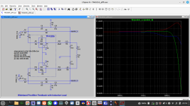
For your reference I add my schematics.
It should be noted the the TPA inputs are driven by a front-end with 2x 2k2 output impedance,
thus the resulting series resistor is 3k2 here.
For your reference I add my schematics.
It should be noted the the TPA inputs are driven by a front-end with 2x 2k2 output impedance,
thus the resulting series resistor is 3k2 here.
Attachments

In the excitement and rush to try out something new, I forgot to take the “before” data. The easiest thing to disable PFFB would be to cut the traces (easy to bridge and enable later if needed). Before doing this probably would be good to disconnect the cap feedback solder joint to get the before shot for this configuration. A lot of work to pull the board from the chassis each time. Not that much work as all wires are on connectors but I am lazy. 😂So if I understand you correctly, you are employing both the TI PFFB circuit and an extra cap from post filter to input?
If this is the TI PFFB circuit, aren't you then not just adding to C_fb .... would be more or less the same as just making these larger (yes know it's a T-filter, but same same nore or less)?
So your distortion and noise figures posted are actually with the PFFB?
bucks bunny's suggestion/implementation is to replace this PFFB circuit with a single cap, right?
View attachment 1402127
The overshoot you see on the oscilloscope, I would think is directly related to the peak on the frequency response. This will be load dependent.
Wouls be good to see before and after pictures.
Thanks to trying it out and for sharing 🙂
I remember buying tiny little SMT slide switches that would let me make the cap feedback mod selectable. Maybe in a new layout that could be added.
@bucks bunny - thank you for sharing your schematic.
Last edited:
Do none of you calibrate your speakers?
Little OT but you missing a lot there.
Just measuring distorsion is fun, I know but... 🙂
Little OT but you missing a lot there.
Just measuring distorsion is fun, I know but... 🙂
Solve, fully agree that in-room freq response is so much more important than THD and that EQ, as well as room treatment and controlled dispersion is the key, but here we are talking about amps, and when designing a new amp it makes sense to try to obtain the best results also regarding THD and Noise 😉
Think I'm close to sending to JLCPCB for my first TPA3255 prototypes (10x10cm 4 layer) 😉
Let's see it it works. Seems to be room enough to implement a ADAU1701 and hopefully a PCM1808 ADC . The 3 opamps on the board can probably be ommited, they form the SE to BAL and Vdd/2 circuit. ADAU1701 can deliver fully balanced output.
But one thing at a time 😉
Nice looking layout! ADAU1701 may have balanced out, but probably not enough current or voltage to drive the inputs. If using PFFB, the gain is only circa 15dB so you are going to need a lot of voltage swing to drive the chip to full output.
Hi xrk971
Thanks 🙂
Yes, I was thinking the same ... so will have to fit op-amp in as well.
OPA1642 now comes in VSSOP ... might help, but not easy to hand solder 😉
And maybe it's a fool's errand and it would probably be more efficient to go for a TAS3251 or a coming TAS3255!
Interface to an ADAU1701:
The ADAU1701 has a maximum output of 2.5Vpp
With PFFB we have around 6x gain, which means with at maximum 51V VCC we need Vin,pp=51/6=8.5Vpp
So we need a gain stage between TPA and ADAU of at least 8.5/2.5=3.4
Member
Joined 2018
Baldin-San,
I was thinking the same thing. The differential ADAU1701 ADC implementation performed extremely well. I was tested in the FreeDSP Catamaran project.
Here's the actual overall ADC - DAC performance of ADAU1701

The output filter is already designed as below. The signal of 1.5V comes from pin40 and 5V is signal swing center.

CyberPit
I was thinking the same thing. The differential ADAU1701 ADC implementation performed extremely well. I was tested in the FreeDSP Catamaran project.
Here's the actual overall ADC - DAC performance of ADAU1701
The output filter is already designed as below. The signal of 1.5V comes from pin40 and 5V is signal swing center.
CyberPit
Last edited:
Hi CyberPit 🙂The differential ADAU1701 ADC implementation performed extremely well
Did you mean ADC or DAC?
.... I was referring to using the DAC output 2 by 2 from the ADAU to form a differential signal to feed the differential input of the TPA3255. If using an active filter on the output of the DAC you could let it include the 4 times gain 😉
Yes the DAC of the ADAU is not bad at all with THD+N of -90dB according to the datasheet. Running differential should give up to 3 dB improvement.
But the ADC of the ADAU1701 is the weak link of only -83dB THD+N .... so to do the rest of the amp justice you will need a separate ADC like PCM1808 or PCM1802
.......
Ok looked at the Catamaran schematics ... ok get it; you are using the 2 input as well in diff mode ...... didn't think about it ... for a plate amp I of course only need 1 input 🙂 ..... good thinking .... further reduces components

Member
Joined 2018
Hello again,
Sorry, I confused you. Using 2 DACs gives 3dB SNR advantage as well.
I have not tested PCM1808 yet, but the measured data shows that it may not be enough for your application.
Here's the same ADAU1701 chip ADC part on the FreeDSP Catamaran Board ADC to DAC single-end through mode distortion characteristic.

Absolutely, useless for this application...😱
This is a PCM1808 on the FreeDSP OCTAVIA ADC to S/PDIF output.

It's quiet and has better distortion performance, but -90dB distortion harmonics level will not be enough for PFFB performance. 🤷♂️
The latest High-performance ADC chips are quite expensive, so I'm expecting PCM1802...🙏
BTW OPA1632 is a quite good device for balanced circuity.
CyberPit
Sorry, I confused you. Using 2 DACs gives 3dB SNR advantage as well.
I have not tested PCM1808 yet, but the measured data shows that it may not be enough for your application.
Here's the same ADAU1701 chip ADC part on the FreeDSP Catamaran Board ADC to DAC single-end through mode distortion characteristic.
Absolutely, useless for this application...😱
This is a PCM1808 on the FreeDSP OCTAVIA ADC to S/PDIF output.
It's quiet and has better distortion performance, but -90dB distortion harmonics level will not be enough for PFFB performance. 🤷♂️
The latest High-performance ADC chips are quite expensive, so I'm expecting PCM1802...🙏
BTW OPA1632 is a quite good device for balanced circuity.
CyberPit
Last edited:
Hi CyberPit-San
Yes, PCM1802 has 3dB better performance at full scale and 6 dB better at -60dB. I haven't tried it, though.
Yes OPA1632 would be a good choice as gain and filter btw ADAU and TPA
I think I'll be just really happy with an overall performance from ADC -> DAC -> AMP of -90 dB ... that is 0.0031% ...
Well this is way too soon ... let's first see the amp actually work 🙂
This is in the ballpark of good 16bit audioI think I'll be just really happy with an overall performance from ADC -> DAC -> AMP of -90 dB ... that is 0.0031% ...
I have to admit that this solution outperforms my simple differential pffb in terms of frequency response.
Can you summarize the changes you made to the nominal values TI recommended for their PFFB implementation?
- Home
- Amplifiers
- Class D
- TPA3255 - all about DIY, Discussion, Design etc