TPA3255 - all about DIY, Discussion, Design etc.drMordor - what are you building?
Akita "AllInOne" Amp based on TPA325x PFFB+ and LLC PSU in one board.
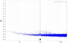
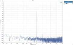
Measurements of three different TPA3255 amps... anyone care to comment on how to interpret the differences?
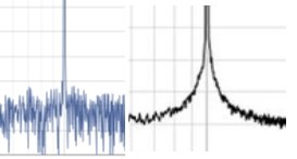
In particular the shape around the base of the test tone (sharp vs slower rise/leading edge) and the noise floor surrounding the test tone:

What effect would this have?
In particular the shape around the base of the test tone (sharp vs slower rise/leading edge) and the noise floor surrounding the test tone:
What effect would this have?
Attachments

Last edited:
Measurements of three different TPA3255 amps... anyone care to comment on how to interpret the differences?
In particular the shape around the base of the test tone (sharp vs slower rise/leading edge) and the noise floor surrounding the test tone:
What effect would this have?
Which TPA3255 amps is it?
XRK and JLesters. I am thinking that the slower leading edge and fall of XRK's TPA3255 is simply there because the noise floor is lower? But if this would actually be audible?
D
Deleted member 148505
XRK and JLesters. I am thinking that the slower leading edge and fall of XRK's TPA3255 is simply there because the noise floor is lower? But if this would actually be audible?
You can ignore the shape since XRK is using a different FFT window function, and uses more averaging. Please check Amir's video on understanding FFT in audio measurements. Understanding FFT in Audio Measurements | Audio Science Review (ASR) Forum
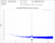
Also you can't directly compare those graphs because they have different setups like output wattage and load resistance dBFS vs dBV etc..
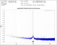
Here's Sylph-D200 @10W 8 ohms. I'm currently creating a complete build so that I can send it for objective measurements (hopefully to Amir)
Attachments
Last edited by a moderator:
I thought that might be the answer - thanks. We now have comparable graphs. Perhaps post these on your website too...
You can ignore the shape since XRK is using a different FFT window function, and uses more averaging. Please check Amir's video on understanding FFT in audio measurements. Understanding FFT in Audio Measurements | Audio Science Review (ASR) Forum
Also you can't directly compare those graphs because they have different setups like output wattage and load resistance dBFS vs dBV etc..
Here's Sylph-D200 @10W 8 ohms. I'm currently creating a complete build so that I can send it for objective measurements (hopefully to Amir)
Just to add - this is a brilliant video. Should be compulsory watching for everyone.
Hi amigos,
Just got my new TPA3255 by HanZao.
This module is pretty unknown so I wanted to test it )
Out of the Box the module comes with the below components :
- 8000uf Rubycon YXF serie Low ESR / 50V
- Buffer caps, Rubycon YXF serie as well
- FIlm caps (MKP) Wurth
- SE Input (using Micro JST connector 2.0)
- DIP 8 OP Amps 5532 (updated with OPA1656)
Need to make a listening test before comparing vs others...
But sounds good at the moment. No Pop sound ON / OFF.
The module is really well protected : Yesterday I was tired and I mounted the power supply in the wrong way and the same for the OP amps... The module has automatically put itself in protection mode.
The Micro JST 2.0 connector is not practical for the SE input but I connected it with a JST 2.54 which is more conventional.
The amp :
- Full alu case
- HanZao TPA3255 module
- 350W LLC PSU / 36V / 9.5A
- OPA1656
- Alps volume pot
- PET Cooper Cables
- AC Filter
Next step : updating Buffer caps.... If I have time )
3E AUDIO TPA3255 and pffb
Hello,
after years of satisfaction with the gainclone,
I was curious about the class D,
so I bought the tpa3255 3e-audio stereo card;
After trying it, I am a little disappointed with
harsh treble and listening fatigue;
gainclone is much better on the mid and high band,
while the tpa 3255 fully wins on the bass,
energetic, deep and dry.
I added the zobel network, now i will implement the pffb,
I wonder why they don't always implement it since
these are few cheap but so important components.
I will not change the op amps,
the ne5532 is used in high end amplifiers and I don't think so
may affect the sound that much.
Most of these cards are copies of TI's EVM,
which I noticed not being the top of the design:
in SE mode, the two opamps are cascaded with gain one,
and this is perfectly useless; in addition also the two electrolytics
on the signal path could be avoided.
The two opamps supply the signal to the two branches,
but one takes the input from the other's output so
asymmetry is created: for example, the feedback capacitor
on the first opamp affects both branches;
this capacitor must also be increased by implementing the pffb.
If the gain of the two opamps is 1, why don't they have
tried to avoid its use, and use the inputs directly
of the chip, as is the case in so many chip-based amplifiers?
(e.g. tripath)
All comments, suggestions and opinions are welcome
Last edited:
Some link, please.....
Just got my new TPA3255 by HanZao.....

Alps pot more info
Hi Dani
Would you confirm what pcb you are using under the pot.
- Alps volume pot
Hi Dani
Would you confirm what pcb you are using under the pot.

Hi amigos,
I gave a test with the HanZao TPA3255 + OPA1692, I think it is the very first time they have been tested here with the TPA325X chip.
AMAZING OP AMPS !!!!!! Wouaaaaaaaaaaaa
An incredible definition! the highs are so good! The voices stand out wonderfully on the front of the stage, it's clean and what a soundstage! Love it )
Here are some videos, they are worth what they are worth but it gives an idea from a distance)
Video 1
HanZao TPA3255 OPA1692
Video 2
HanZao TPA3255 OPA1692 B
- Home
- Amplifiers
- Class D
- TPA3255 - all about DIY, Discussion, Design etc