The attachments where helpful frammis. I redid the outputs and C32/C47 based on them.
Thanks for being patient with me Doctormord. I finally got some grasp of current return loops. I think the return paths to the buck are shorter now with the combination of top and bottom gnd plane.
I misplaced 2 of the MLCC's, they were for the supervisory circuit. The MLCC's for the lm5010 are 2.2uF and 0.1uF. I have been reading application documents from TI and other sources. While I know the calculations to get the filter frequency, I am not sure what specific range of frequency that is suppose to be removed. Out of my element. I am adding the 10nF near the buck along with the two original.
As for the header, I am planning to put the jumper underneath the board.
Will the 12V trace underneath the AFE inputs cause problems?
Attachments

Did you got thermal pad finally fixed now?
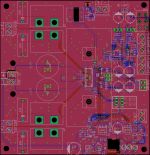
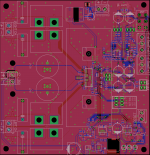
You also finally want to open the middle slot at the bottom plane between the outputs. There's no need to put the two output traces together like this. The you additionally can get rid of the 4 vias at this "Gnd stub" on the top . (That rectangle right next to the bulk caps.
Then think about the jumpers under the heatsink - even when mounted from the bottom, won't the header touch the heatsink anyway because trough hole? And what about mounting distance to a bottom plate or case.
Give this LDO some more thermal vias next to the tab. (like 0.5-0.6mm diameter)
Good progress so far. 🙂
Last edited:
trashcanz,
Great progress! The PVDD decoupling looks good now. I agree with Dr. Mord's comments about the middle slot between the outputs.
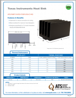
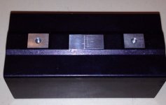
I also have questions about clearance. Maybe you already accounted for this, but the TPA3251 TSSOP package is so thin, you might not have enough vertical clearance for the MLCC's unless you use a machined heat sink. The TI EVM sink is available from Digi-key (Advanced Thermal Solutions ATS-TI10P-519-C1-R3) and pictured below. You can see the little pedestal for the die mounting pad that allows lots of clearance underneath.
The heat sink fins or length could be cut down for audio. TI tends to use overkill sizes on their EVMs.
Great progress! The PVDD decoupling looks good now. I agree with Dr. Mord's comments about the middle slot between the outputs.
I also have questions about clearance. Maybe you already accounted for this, but the TPA3251 TSSOP package is so thin, you might not have enough vertical clearance for the MLCC's unless you use a machined heat sink. The TI EVM sink is available from Digi-key (Advanced Thermal Solutions ATS-TI10P-519-C1-R3) and pictured below. You can see the little pedestal for the die mounting pad that allows lots of clearance underneath.
The heat sink fins or length could be cut down for audio. TI tends to use overkill sizes on their EVMs.
Attachments
Thanks for the help fellas, greatly appreciate it!
You are correct Doctormord, I looked at the lm5010 and there is a thermal pad there. I forgot about it reading the datasheet. The ground vias you suggested with solid bottom plane should handle the heat dissipation.
That is the exact heatsink I have in front of me, frammis. It is large indeed. I imagine that a very compact board can be made with a smaller heatsink/inductors like doctormord's. My board size as of now is 125x125 mm.
I measured the headers I am using and there should be plenty of clearance. I do have to get extra tall standoffs because of the capacitor and jumpers underneath but I am using a large enclosure for this.
I am getting board made with 2 oz. copper. I am going to spend the next few days going over and cleaning the layout some more before I send it off.
Thanks again!
Attachments
Hmm, 2 more notes:

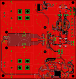
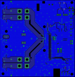
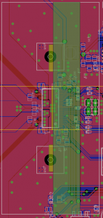
As this is isolated you don't want to have radiation into the isolated lines or vice versa from the DCDC. Additionally, theres no local decoupling at the converter at the in side.
Either remove the GND-fill in this area completeley or additionally do a local V- fill.
Optional: put a "AC/HF" coupling cap from V- to GND for EMI reasons. (You normally wont need it, but who knows.) Should be 2n2 2KV, so a small X7R ceramic disc through hole is fine.
Secondly:

Assuming the Eagle image is with the correct aspect ratio, it seems your heatsink footprint is way of from the dimensions shown in the datasheet. Then, you might have a clearance problem with bootstrap and decoupling if their footprint height is >= 1mm.
As this is isolated you don't want to have radiation into the isolated lines or vice versa from the DCDC. Additionally, theres no local decoupling at the converter at the in side.
Either remove the GND-fill in this area completeley or additionally do a local V- fill.
Optional: put a "AC/HF" coupling cap from V- to GND for EMI reasons. (You normally wont need it, but who knows.) Should be 2n2 2KV, so a small X7R ceramic disc through hole is fine.
Secondly:
Assuming the Eagle image is with the correct aspect ratio, it seems your heatsink footprint is way of from the dimensions shown in the datasheet. Then, you might have a clearance problem with bootstrap and decoupling if their footprint height is >= 1mm.
Attachments

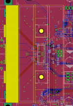
As i can't find any more detailed heatsink dimensions, i extracted the outline from the TAS5622 EVM manual:
http://www.ti.com/lit/ug/slau376a/slau376a.pdf
The dimensions are equal to whats shown in the heatsink datasheet.
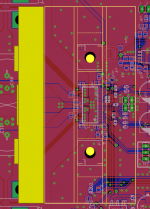
When scaled to your heatsink outline, the drills are way off:

When scaled to drills, you may run into clearance problems even more:

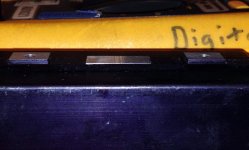
I'm a bit unsure if they come predrilled or not. The heatsink from the 3251 EVM looks like this:


Images: J.B. - Texas Instruments
http://www.ti.com/lit/ug/slau376a/slau376a.pdf
The dimensions are equal to whats shown in the heatsink datasheet.
When scaled to your heatsink outline, the drills are way off:
When scaled to drills, you may run into clearance problems even more:
I'm a bit unsure if they come predrilled or not. The heatsink from the 3251 EVM looks like this:
Images: J.B. - Texas Instruments
Attachments
Hey guys...
Great thread and work on the new design!
Jumping ahead a few steps to me buying a completed kit. One of the few I have found is YJ's build here with very scant details:
Yuan Jing Audio - TPA3251D2 High Performance Ultra-HD Class-D Stereo Amplifier Board [175W x 2] - USD $38.00
Does anybody have any experience or feedback with this unit. Or any better suggestions?
Cheers
Dean
Hello thunk303,
The quality of the Yuan Jing is unknown since it has not been released. However, at 38 usd you will have to expect some low quality components. It is a surprisingly low price, maybe they are getting crazy low bulk prices?
Anyways, I would recommend to get a board with a proven design from forum member gmarsh. Here is his group buy thread.
Doctormord,
I double check the heat sink dimensions and clearance on Eagle. Everything seems to check out. I think that scaling is off since I used snipping tool to get the screen captures. I added your suggestions onto the dc converter.
Thanks!
Doctormord,
I double check the heat sink dimensions and clearance on Eagle. Everything seems to check out. I think that scaling is off since I used snipping tool to get the screen captures. I added your suggestions onto the dc converter.
Thanks!
Strange as the mounting holes come out in perfectly round shape. So if it fits, good. 🙂
Nice to see some progress in this thread! Anyone coming out with a design for sale soon? I have two 5630 boards I would like to replace with something better and equally powerful. Gmarsh, how is your design coming along?
I want to thank all involved for making this thread such a useful and constructive discussion.
A few weeks ago I 'discovered' the TPA3152D2 when TI announced it's big brother, the TPA3255 and to my disappointment I found it was
'preliminary' :-(
It appeared the lower power TPA3152D2 was pin compatible, so spurred on by that, I ordered samples from TI and got started on my own
design. I've been slowly working on this for the past few weeks as time permits, and now luckily I found this thread!
After reading thru 80 pages of discussion (yes I actually did), I'm a lot clearer on the less documented 'features' of this chip and feel
confident I can get a working design out. I've used other Class-D chips in the past and find it takes some care and attention to layout to
get the best out of them.
I have most of the schematic done, just the shutdown / fault / clip logic and indicators to do.
Will post a schematic as soon as I have this figured out.
Cheers,
Len.
Group buy is started, got an uncomfortably large number of orders for a handbuilt prototype 🙂Nice to see some progress in this thread! Anyone coming out with a design for sale soon? I have two 5630 boards I would like to replace with something better and equally powerful. Gmarsh, how is your design coming along?
Sent from my Nexus 4 using Tapatalk
Did you tested your 3250 design already? Any measurements on thermal performance?
Ah, and, still missing the package from Canada. 😀
Ah, and, still missing the package from Canada. 😀
Yeah, I never mailed it 🙂 I ended up raiding it, there was a full set of Wiener inductors in there and I was short a set. You'll get a package eventually, I'll replenish the box when I make the big group buy order and throw in more goodies.
I'm using a TPA3250 instead of a 3251, and heatsinking to the PCB with many vias under the IC to a largely unbroken ground plane. And I've got plenty of room for an even bigger thermal pad to the chassis, for applications where the card will be dissipating a lot of power. Don't have the thermal calculations handy but they looked good when I ran them.
Haven't built it yet. This run is for the prototype. I've warned that in the group buy thread, that there's a possibility the amp may have problems and finished/working units may be delayed... but people are still ordering it. Hopefully everything works out.
Looking forward for the results - in any aspect. 🙂 (Also in the performance of the flybuck implementation)
This run is for the prototype. I've warned that in the group buy thread, that there's a possibility the amp may have problems and finished/working units may be delayed... but people are still ordering it. Hopefully everything works out.
We have faith 😀
It's now too delicious to resist!
Inductors
have read much in this thread about using Inductors from coil craft and ice but what of other makes such as sagami they seem to make coils for class d amps any one tried these before ? R&D,Manufacture and Sales of Coils | SAGAMI ELEC CO., LTD.
have read much in this thread about using Inductors from coil craft and ice but what of other makes such as sagami they seem to make coils for class d amps any one tried these before ? R&D,Manufacture and Sales of Coils | SAGAMI ELEC CO., LTD.
The problem is availability, haven't found a supplier in Europe. Some series are available from rs-components but also restricted to the (north) asian area. Then there is inductor.com, but dunno if they deliver to Europe.
- Home
- Amplifiers
- Class D
- TPA3251d2