? I don't use a seperate PCB, SE to Diff is already onboard.
Really? I got confused then with what is there on your website. I thought the board with the volume control also did SE to BAL as a way of giving options for the input stage.
no theyre just break-away (fake-away) attenuator boards, they do have a separate ground plane tho, which is something!
Last edited:
using differential on any class D is a definite advantage ( RE common mode noise ), which is why I lose interest in most implementations. hence folks with input transformers or buffer boards are way ahead. but when not included on cheap amps aren't so cheap or easy anymore.
how bad is the common mode noise? basically really really bad and gets worse with more power out. This is the (dirty) secret of SMPS and class D
Infinia, interesting. But wouldn't the common mode noise be switching noise and outside the audio band & filtered? Or is it other noise introduced at the inputs introduced intrinsically by the switching mechanism? Do you have any links to read up more about this? As per earlier posts about the datasheet graphs and SE/balanced modes this difference is evident in the graphs.
its some error term of the modulated output carrier added to the SE input signal.
its a complex delayed signal so basically 'the grunge' kills the dynamic range seen at the input of the amp is how I look at it.
from EMC perspective http://www.hottconsultants.com/pdf_files/APEC-2002.pdf
also can search "CM noise" terms related to CMOS ground bounce in digital systems.
also" " " isolation amp in instrumentation
this is a system issue!, turns up with your PCB layouts with your sources.
its a complex delayed signal so basically 'the grunge' kills the dynamic range seen at the input of the amp is how I look at it.
from EMC perspective http://www.hottconsultants.com/pdf_files/APEC-2002.pdf
also can search "CM noise" terms related to CMOS ground bounce in digital systems.
also" " " isolation amp in instrumentation
BTW I think this is NOT shown on any TI charts per se. because the amp is tested alone. the CM = 0 by definition, or they minimize it with test gear they picked. (the THD meter and amps ground is bolted together at earth ground = zero CM)As per earlier posts about the datasheet graphs and SE/balanced modes this difference is evident in the graphs.
this is a system issue!, turns up with your PCB layouts with your sources.
Last edited:
OK - so this is extra noise just inherit in switching designs (and feedback can't fix) which with a differential input can be significantly reduced just because it is differential (ie. not specific to it being a class-D amp).
I hadn't thought of it that way, which gives a stronger case for using this amp with differential inputs instead of SE (which was my original design intent, for simplicity) especially if the TI graphs aren't showing the common noise. Probably also the reason why Hypex prefer their Class-D amps be connected with differential inputs.
I hadn't thought of it that way, which gives a stronger case for using this amp with differential inputs instead of SE (which was my original design intent, for simplicity) especially if the TI graphs aren't showing the common noise. Probably also the reason why Hypex prefer their Class-D amps be connected with differential inputs.
its some error term of the modulated output carrier added to the SE input signal.
its a complex delayed signal so basically 'the grunge' kills the dynamic range seen at the input of the amp is how I look at it.
from EMC perspective http://www.hottconsultants.com/pdf_files/APEC-2002.pdf
also can search "CM noise" terms related to CMOS ground bounce in digital systems.
also" " " isolation amp in instrumentation
BTW I think this is NOT shown on any TI charts per se. because the amp is tested alone. the CM = 0 by definition, or they minimize it with test gear they picked. (the THD meter and amps ground is bolted together at earth ground = zero CM)
this is a system issue!, turns up with your PCB layouts with your sources.
Certainly the amp is tested without cm-noise. The problem with cm-noise is that due to imperfect symmetry it will be transformed to dm-noise which will disturb your circuitry. In most cases using differential inputs will be of some advantage but proper EMI shielding of noise sources should be the goal.
no theyre just break-away (fake-away) attenuator boards, they do have a separate ground plane tho, which is something!
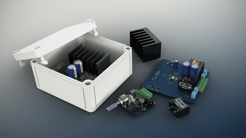
This break-away boards is just to make the amp boards smaller or to put the pot in a different place.
@5th element,
the confusing boards are a completely different amplifier. These are TPA3132D2 amplifiers just to show them in size comparison.
the confusing boards are a completely different amplifier. These are TPA3132D2 amplifiers just to show them in size comparison.
Oh! 😱
That makes things a little clearer! 😀
Once again, the small one is 50+50W TPA3132D2, a TPA3116 in QFN package. If you want a bare PCB, I'll put one in the post tomorrow (with the 3251)
Once again, the small one is 50+50W TPA3132D2, a TPA3116 in QFN package. If you want a bare PCB, I'll put one in the post tomorrow (with the 3251)
I have a number of TPA3118 amplifiers of my own already so that's okay, it would probably just sit on a shelf somewhere and not get used. Thank you for the offer though.
Once again, the small one is 50+50W TPA3132D2, a TPA3116 in QFN package. If you want a bare PCB, I'll put one in the post tomorrow (with the 3251)
Hi
This is a general offer? 🙂
For the PCB? Sure, why not. 🙂
What are you charging for the miniature bare 3132 boards?
German customs are so damn slow.. :|
@5th, chip is on its way.
Many thanks Dr.
Have you managed to have a good listen to them yet?
No, because PCBs still not arrived. (But in Germany since 08/18 -> German customs)
Man that must be infuriating!😡
No, because PCBs still not arrived. (But in Germany since 08/18 -> German customs)
One of my shipments went to Germany, 4 days to get there, a few weeks in customs.
🙂
- Home
- Amplifiers
- Class D
- TPA3251d2