Heatsink gets heat from mainheatsink=pcb, you improved connection to pcb ?
Measured temperature of (purple) heatsink doesn't tell much when connection to pcb is not good, what is temperature of pcb below chip or ground next to chip or on negative pin capacitors ?
Mosfet circuit used by FX isn't on 3250 evm I think, MCU isn't on 3250evm either, so FX tried to make own protection maybe ???, how to know fault/protection tripping is indeed tpa3250 it might be FX own circuitry ???
The 0V problem has more to do with pcb ground layout than with external psu, seems like external psu is powerfull enough for the Sonus speakers (=easy load), or doesn't seem reason the FX reaches protection.
Hi irriebo
what do you mean with the 2nd + 3nd chapter in your answer? is it refered to my measurements. sorry but its for me confusing.😕
please step by step...i am a noob...
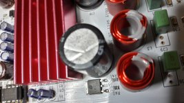
Before it was sawed it was 90х50x26(h) mm. Now the capacitors do not touch the heatsink. But they still heat up a little, apparently through the board.
By the way, the height of the original heatsink was 15 mm only. And the new one is much larger even after sawing.
No, no contact to housing. It's not easy to do, 'cause the top and bottom covers move.
ok..fine so 26mm high is possible..good to know.
yes you are right the upper and the lower case are exactly at this high of your heatsinks side fins.....not easy....
i try to make some pics of the ceramic resistor connection to the buttom case....
Heatsink gets heat from mainheatsink=pcb, you improved connection to pcb ?
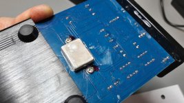
I replaced plastic washers between the heatsink and the board with aluminum ones and added thermal grease. So I think connection was improved.
...how to make the ceramic colling implementation ...
hi
i got during my test just 34°C at to buttom plate, it feels more because i think my measurement tool gets trouble at black colored alu case without contrast to measure correctly. it feels more then human skin warm...so about 37°C...so it works good.
here are my pics :
turn the amp other way round and us thermal paste thin.
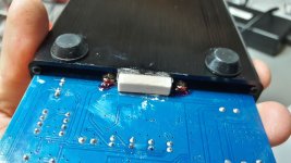
pic 1: 2 pcs of isolator (glimmer i guess) under the resistor and 2 pcs on top. its more then 5,1mm...but soory i didn measure it..
pic 2 : be gently to get the alu buttom case over the pcb....do not crack the pcb !!
pic 3: recheck if the ceramic resistor is still in the needed position....not easy to make pics to catch this...sorry..chris
hi
i got during my test just 34°C at to buttom plate, it feels more because i think my measurement tool gets trouble at black colored alu case without contrast to measure correctly. it feels more then human skin warm...so about 37°C...so it works good.
here are my pics :
turn the amp other way round and us thermal paste thin.
pic 1: 2 pcs of isolator (glimmer i guess) under the resistor and 2 pcs on top. its more then 5,1mm...but soory i didn measure it..
pic 2 : be gently to get the alu buttom case over the pcb....do not crack the pcb !!
pic 3: recheck if the ceramic resistor is still in the needed position....not easy to make pics to catch this...sorry..chris
Attachments

Last edited:
Do you all think heat is a significant problem? If so, why? I got the error light, but the thought here was that was under-voltage.
I may still do a little to work on the heat, but I am not sure it is necessary. Have any of you looked at the "heatsink cooling thermally conductive thermal pads"? I thought those might work underneath the board to bridge the chip/board to the case.
But all that said, I am not sure that heat is a problem.
Cool! I'll try this if find such resistor or something like this.hi
here are my pics
Do you all think heat is a significant problem? If so, why? I got the error light, but the thought here was that was under-voltage.
I may still do a little to work on the heat, but I am not sure it is necessary. Have any of you looked at the "heatsink cooling thermally conductive thermal pads"? I thought those might work underneath the board to bridge the chip/board to the case.
But all that said, I am not sure that heat is a problem.
hi Swank42
i did some measurements at 13Watt per channel - 8ohms each channel for approx 90min. as you can read in the previous posts. i personally want to squeeze out the actual amplifier together with everybody who is interested.
yes the undervoltage is an issue. next test will be wiht my psu´s...
we will see.
chris
Last edited:
Cool! I'll try this if find such resistor or something like this.
😀😎😀
When nothing is attached to purple heatsink it will get to airtemperature, the air heated by the coils. You measured heatsinktemp to find clues for tpa3250 chip temperature, i guess. Screwmounting holes' copper has soldered connection to tpa3250 heatpad, if they mounted (soldered heatpad) 3250 correctly, "Rubycon" capacitor negative pins then have copper connection to 3250 heatpad, tpa3250 groundpins always have connection to tpa3250 heatpad too, pin 25/26/33/34/41/42. Temperature measurements of those can give you an idea of tpa3250 mosfets-temperature and maybe indication heatpad is soldered to pcb or not. (On some chinese tpa3118 boards they "forgot" to put solderpaste below tpachip).
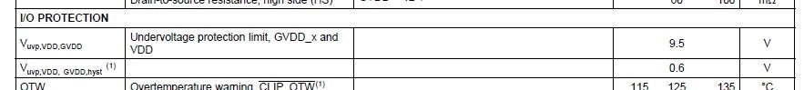
But again, temperature needs to be above 150 degrees for tpa to trip overtemperature protection, 24V PSU and music are not likely to get chip that hot. 3250's own protection.
I don't know what FX added.
I do know for example that on a 3118 ampboard a mcu was added to controll startup/down, on that ampboard when pushing 1.5ohm speakers that MCU sees a voltage that causes the MCU to think power is down and the MCU then causes a powerdown and power up sequence, as if protection tpa3118 is tripping, not overtemperature btw, but the overcurrent protection is (ex/)sus-pected because of 1.5ohm load. Things get added to tpachip that might behave in a way that resemble the tpaprotection tripping.
For tpa3250 you have separate lower voltages like 3.3V? and 12V? for other parts of chip, and probably for MCU too (I believe TI discribes 0V difference regulators/tpachip/opamps left/right being cause of distortionincrease on first EVMboard). At those lower voltages the margin for undervoltage could be relatively small and a difference in 0V for voltageregulator and 0V for chip and or 0V for mcu caused by the highcurrent highfrequency injected into ground by the outputfilter, could be enough ?
For tpa3250 you have separate lower voltages like 3.3V? and 12V? for other parts of chip, and probably for MCU too (I believe TI discribes 0V difference regulators/tpachip/opamps left/right being cause of distortionincrease on first EVMboard). At those lower voltages the margin for undervoltage could be relatively small and a difference in 0V for voltageregulator and 0V for chip and or 0V for mcu caused by the highcurrent highfrequency injected into ground by the outputfilter, could be enough ?
i cannot follow you......do you metioned this:
chapter 7.5 from the TI datasheet of tpa 3250
chris
Attachments

http://www.ti.com/lit/an/slaa719/slaa719.pdf
What happens there is on pcb that has "more" groundplane than FX's pcb
What happens there is on pcb that has "more" groundplane than FX's pcb
http://www.ti.com/lit/an/slaa719/slaa719.pdf
What happens there is on pcb that has "more" groundplane than FX's pcb
hi irriebo
yes i accept that the FX is not the best construction.😉 i have a TI 3251EVM board and i can say thats it.😀
so the answer is that the fx amps i on its limit.
as you can see at my next test there is something strange with the irf temp at 4 ohms load. my idea was to use the power psu (corally 15V/16A) which i tested posts before so undervoltage should be not the topic.
same situation sweep 10Hz-25khz -1Vrms input into both RCA inputs. 4ohms load, about 8,3 -9,68V, 2 -2,32 Amps --> about 22WATT
....but i get the same strange over temp at the IRF9530- like 8ohms load and 2VRMs input aat both RCA ----- , e.g. 60°C after 3:20 min and after 5:30 min 75°C. i stopped the test
any ideas????
P.S: i excuse my self because i wrote temp test - its a load test with consecences🙂
Attachments
Last edited:
I haven't seen drawing what irf is doing, maybe it is in thread earlier, but maybe I skipped it then 🙂 Is it used as powerfollower/regulator/filter too ?
I haven't seen drawing what irf is doing, maybe it is in thread earlier, but maybe I skipped it then 🙂 Is it used as powerfollower/regulator/filter too ?
its written at page 23 #230... it was an idea. but until now nobody really checked.
this willbe a task for tomorrow for me...i try my best.🙂
...LM317 Regulator
refered to the post at page21 #208...i was rechcking my amp
during 24V psu i measured the LM317. amp is v3 version -blue
actually the resistor values near the LM317 are SMD: R41=2400 and R40 = 4301
so according to the calculator here:
LM317 Voltage Calculator | REUK.co.uk
if the values are exact = 23,65V out
my measurements:
i measured pin 3 in = 23,87V, pin 4 out = 22,32V, pin 2 adj = 21,14V
my question is: is this regulator working correctly or not?
according to LM17 datasheet. chapter 7.4.1
7.4.1 Normal Operation
The device OUTPUT pin will source current necessary to make OUTPUT pin 1.25 V greater than ADJUST
terminal to provide output regulation.
my interperetation is yes because : Vadj + 1,25V < = Vout
thanks and good night...(22:41)
chris
Good night Chris....
I don't want to disturb your sleep but......
You are on the limit of a problem: You have 1.55V between input and output. The TI datasheet says you should have 3V minimum. My guess is it may work until some 2V input-to-output, but you only have 1.55V. Your LM317 is starting saturating. Further, your 1.55V difference is measured as an average input voltage. With some voltage ripple, your input voltage is even lower just before re-charging by the transformer.
How can we verify that the LM317 is in saturation? - your difference between the output pin and the reference pin is 1.18V. TI states this voltage difference to be in-between 1.20V and 1.30V. You have only 1.18V because it has lost regulation.
Input voltage up, Chris!
But first, good night - sweet dreams.
Last edited:
Good night Chris....
I don't want to disturb your sleep but......
You are on the limit of a problem: You have 1.55V between input and output. The TI datasheet says you should have 3V minimum. My guess is it may work until some 2V input-to-output, but you only have 1.55V. Your LM317 is starting saturating. Further, your 1.55V difference is measured as an average input voltage. With some voltage ripple, your input voltage is even lower just before re-charging by the transformer.
How can we verify that the LM317 is in saturation? - your difference between the output pin and the reference pin is 1.18V. TI states this voltage difference to be in-between 1.20V and 1.30V. You have only 1.18V because it has lost regulation.
Input voltage up, Chris!
But first, good night - sweet dreams.
good morning Fauxfrench

thanks for your help. i think yesterday i was too tired to check this.😛 i read a lot of datasheets but don´t realized this....shame on me...😉
with my DMM i measure : (tripple check) white (V5) and blue (v3) pcb are the same
R41=2400....236ohms and R40 = 4301.....3020ohms ??
if i use the calculator:
with this values R1= (R41)= 236 and R2=R40= 3020........i get : 17,25V
so what ????😕😕
chris
Attachments
- Home
- Amplifiers
- Class D
- TPA3250 somebody is listening?