I used an electrolytic capacitor as the 10µ capacitor, is that fine?
Yes that's fine, and you have it reasonably close to the supply pins.
I would start with replacing the boostrap capacitors with X7R ceramics.
That there may be part of your problem. C1-C5 should all be monolithic ceramic caps. Inductively wound caps (rolled foil) can cause many problems in high speed switching circuits. There's a reason you see all those little chip ceramic caps next to IC's on modern digital PCBs instead of standard film types.C3 and C4 are plastic capacitors, I don't know if they are low-esr or other special capacitors.
That there may be part of your problem. C1-C5 should all be monolithic ceramic caps. Inductively wound caps (rolled foil) can cause many problems in high speed switching circuits. There's a reason you see all those little chip ceramic caps next to IC's on modern digital PCBs instead of standard film types.
Tried switching them to ceramics, didn't work. 🙁
I've built quite a few different PCB iterations using this IC and they have all worked (and I'm no professional by any means). Some had hum from bad grounding, but they did work.
Would it be possible to get the layouts and masks (just as a gif file), I would like to try out some of them?
Would it be possible to get the layouts and masks (just as a gif file), I would like to try out some of them?
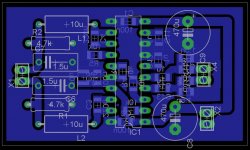
I really don't think my layout will be of much use. It uses 1uF 100V X7R ceramics for every cap except the main power caps and 100nF decoupling caps.
The board is double sided and all the ground pins are soldered to the top side ground plane.
Attachments
I really don't think my layout will be of much use. It uses 1uF 100V X7R ceramics for every cap except the main power caps and 100nF decoupling caps.
The board is double sided and all the ground pins are soldered to the top side ground plane.
Thanks, but a plain gif file would be more useful (I would need to make a negative mask) if it's not too much trouble. 🙂
Anyways, what do you mean with it not being of much use?
Thanks, but a plain gif file would be more useful (I would need to make a negative mask) if it's not too much trouble.
Sorry, the program I use doesn't have an option to output/save as a GIF. I'm sure you can take the PDF I posted and convert it somehow. I don't have time to figure it out right now though.
Anyways, what do you mean with it not being of much use?
Well, I just meant unless you have the exact parts I used you will have to do a lot of improvising.
OK, I don't know if this is what you were looking for, but I gave it a shot anyway.....
Attachments

Last edited:
Yeah, that's what I was looking for. Thanks
I have SMD components around, so I can probably figure out something. If you can send a picture of layout (with component values), that would be nice too.
I have SMD components around, so I can probably figure out something. If you can send a picture of layout (with component values), that would be nice too.
Last edited:
I have SMD components around, so I can probably figure out something. If you can send a picture of layout (with component values), that would be nice too.
I don't know when or even if I would be able to do that. I don't even make those notes or diagrams for myself as I find it tedious. I just rely on memory. 😱
I think the best I can do for you is show you pics of a different version of the board I made and let you try to reverse engineer it a bit. It's a simple enough circuit.
http://www.diyaudio.com/forums/class-d/124318-my-tpa3122d2n-btl-proto-6.html#post1872915
I will mention there are three "vias" that are just wires soldered from the ground plane to pads on the bottom. One is near the gain jumpers and the other two are on the ends of the output filter caps.
Sorry, that's the best I can to right now.
Oh, you didn't design it with a CAD program? 🙂
Not a proper one. 😱
I use Pad2Pad and lay out everything manually. Netlists make me angry.

Now it works otherwise fine, but it still has one problem: you hear a high-frequency whine from the speakers, which I suspect is the difference between the switching frequencies of the two amps. I tried to regulate the voltage supply to the preamp, but this didn't help. Also, this whine isn't heard when the inputs aren't connected, so I suspect it's because of the preamp.
Last edited:
Now it works otherwise fine, but it still has one problem: you hear a high-frequency whine from the speakers, which I suspect is the difference between the switching frequencies of the two amps. I tried to regulate the voltage supply to the preamp, but this didn't help. Also, this whine isn't heard when the inputs aren't connected, so I suspect it's because of the preamp.
i have the same problem,too
- Status
- Not open for further replies.
- Home
- Amplifiers
- Class D
- TPA3122 doesn't work