Hi indika,
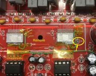
The chokes are the yellow rings (cores) with copper-wire windings.
I will explain why I suggest to remove the two chokes with reference to the schematic I made.
Considerable current drawn by a TPA3116 chip (from “+” to “-”) is either a load-current (arrows “L.cur”) or an internal current (arrow “I.cur”). Without a signal at the input, a Load current may be due to a wrong signal level at the input of the TPA3116. Such we have a chance to repair. An important Internal current should not exist and if it is nevertheless there, it is likely to be due to a defect TPA3116 chip. That your speaker-cone jumps in-and-out shows that you have an important Load current but perhaps this is because you have an important Internal current as well. How do we check if you have an important Internal current? You have to prevent the Load current from flowing.
Preventing the Load current from flowing would be achieved by removing the speaker, thus cutting at the points “c”. But cutting at the points “c” would leave the LC output filter un-dampened (the load provides the dampening) if a resonance is exited. Such would put a risk to the circuit – see the very first postings in the very long TPA3116 thread (by DDAPKIS). Thus, just removing the speaker would be unsafe. Therefore, we have to disconnect the output filter while testing for current consumption. This is done by cutting (de-soldering) at the points “a”. BUT, a rather heavy choke fastened to the PCB with only one lead will move around and risk causing a short-circuit to something else. This is why I recommend removing the two chokes by cutting the circuit (de-soldering) at both the points “a” and “b”.
When the output filter and the speaker are no longer connected to the TPA3116, only the Internal current (“I.cur”) can cause a high current consumption. Said in other words, if your amplifier plays well with the remaining stereo channel and the sub, and the supply voltage ripple is low, we have a chance of making the faulty channel work. If the amplifier does still not function well and the supply voltage ripple is high, it is a sign that the Internal current is high. A high Internal current is likely to be due to “shoot-through” current in a push-pull stage of the TPA3116, used for the faulty channel. Such is most likely a TPA3116 chip defect that cannot be repaired.
NO SUPPLY VOLTAGE when you remove the chokes!
I hope that this explanation makes it clear why I suggest removing the two filter chokes.
Attachments

Hi indika,
The chokes are the yellow rings (cores) with copper-wire windings.
I will explain why I suggest to remove the two chokes with reference to the schematic I made.
Considerable current drawn by a TPA3116 chip (from “+” to “-”) is either a load-current (arrows “L.cur”) or an internal current (arrow “I.cur”). Without a signal at the input, a Load current may be due to a wrong signal level at the input of the TPA3116. Such we have a chance to repair. An important Internal current should not exist and if it is nevertheless there, it is likely to be due to a defect TPA3116 chip. That your speaker-cone jumps in-and-out shows that you have an important Load current but perhaps this is because you have an important Internal current as well. How do we check if you have an important Internal current? You have to prevent the Load current from flowing.
Preventing the Load current from flowing would be achieved by removing the speaker, thus cutting at the points “c”. But cutting at the points “c” would leave the LC output filter un-dampened (the load provides the dampening) if a resonance is exited. Such would put a risk to the circuit – see the very first postings in the very long TPA3116 thread (by DDAPKIS). Thus, just removing the speaker would be unsafe. Therefore, we have to disconnect the output filter while testing for current consumption. This is done by cutting (de-soldering) at the points “a”. BUT, a rather heavy choke fastened to the PCB with only one lead will move around and risk causing a short-circuit to something else. This is why I recommend removing the two chokes by cutting the circuit (de-soldering) at both the points “a” and “b”.
When the output filter and the speaker are no longer connected to the TPA3116, only the Internal current (“I.cur”) can cause a high current consumption. Said in other words, if your amplifier plays well with the remaining stereo channel and the sub, and the supply voltage ripple is low, we have a chance of making the faulty channel work. If the amplifier does still not function well and the supply voltage ripple is high, it is a sign that the Internal current is high. A high Internal current is likely to be due to “shoot-through” current in a push-pull stage of the TPA3116, used for the faulty channel. Such is most likely a TPA3116 chip defect that cannot be repaired.
NO SUPPLY VOLTAGE when you remove the chokes!
I hope that this explanation makes it clear why I suggest removing the two filter chokes.
Ohh..Thanks baby😚😚😚 understood like a charm🙏💪💪💪
Ohh..Thanks baby😚😚😚 understood like a charm🙏💪💪💪
So and so..I just removed first defective channel coils and powered up the circuit..it seams ok at lowest volume..when I increased the subwoofer channel is starting to popup continuously..Then I remove that channel coils too..now only single channel...so result is attached as a video..you can listen..it seams to be a popping some other way..bad luck😏😢😢
Gofile
thanks,
best regards,
indika
Hi indika,
Many thanks for the video. It doesn't sound good.
Do you have an oscilloscope?
Do you have a digital multi-meter (DMM)? I assume yes.
If you have a DMM, please measure the supply voltage to the board to see if the supply voltage remains more-or-less constant when the click is heard from the speaker or the voltage goes up and down? The fact that the IC can give some sound is good but it may still have an internal fault.
It sounds like a protection (there are many) that shuts the chip down for a moment and then let the chip operate again.
The board has two 8-pin ICs, what type are they?
Hi indika,
Many thanks for the video. It doesn't sound good.
Do you have an oscilloscope?
Do you have a digital multi-meter (DMM)? I assume yes.
If you have a DMM, please measure the supply voltage to the board to see if the supply voltage remains more-or-less constant when the click is heard from the speaker or the voltage goes up and down? The fact that the IC can give some sound is good but it may still have an internal fault.
It sounds like a protection (there are many) that shuts the chip down for a moment and then let the chip operate again.
The board has two 8-pin ICs, what type are they?
No I haven't oscilloscope..Yes..I have multimeter...ok..I will test and tell you..It was a laptop charger..most probably voltage must be smooth...yes It has two tpa3116 ic chips..thanks, indika
Member
Joined 2018
XH-M139 as a Troublemaker
Hello indikaperera-San,
I met the same issue(s) on this board.
The toroidal core inductors are easily saturated as a Core-Memory.
Once saturated, then the inductance shall be extremely low even the power-off. I guess your toroidal core inductors works as a just wire now.
According to my experience about this board, I can say some of the output channel must be dead. (Most of case, It required to swap the issued chip(s).
Degaussing the core should be one of way to fix this situation, but my recommendation is change the all toroidal core inductors to the Hi-Current capable Metal-Alloy inductor or make a gap (cut the circle of core)
You can see the much design issues of this board in my web page...
Destop 2.1 channel Amprefire Modification
Regards,
CyberPit
It is not the two TPA3118 I meant. It is the two OP-AMPs or something like that.
Hi..mate..there is no current fluctuations of supply voltage and two ic chips are tpa3116d2. Actually when I look at the board there is nothing wrong and there are not much complex parts to worry..I think most probably the two ic chips may be the problem.isn't it? anyway I have to purchase rework station before replacing ics..i stuck in the middle due to covid 19. nothing can buy even ics..����as you said was it protection..why it is activated..there is nothing wrong with power, speakers..etc? anyway thank you so much for the efforts and specially the time that taken to help me..much appreciated..thanks buddy..��
Last edited:
Hello indikaperera-San,
I met the same issue(s) on this board.
The toroidal core inductors are easily saturated as a Core-Memory.
Once saturated, then the inductance shall be extremely low even the power-off. I guess your toroidal core inductors works as a just wire now.
According to my experience about this board, I can say some of the output channel must be dead. (Most of case, It required to swap the issued chip(s).
Degaussing the core should be one of way to fix this situation, but my recommendation is change the all toroidal core inductors to the Hi-Current capable Metal-Alloy inductor or make a gap (cut the circle of core)
You can see the much design issues of this board in my web page...
Destop 2.1 channel Amprefire Modification
Regards,
CyberPit
Hi..Mate...
I have already seen your article before I came to this forum..but it is much complicated me to understand due to my lack of knowledge..I think you did several modifications to eliminate existing errors but my problem is this board is not working atleast as they provided. I have sill doubt(may be a stupid question..lol) why we can't check IC chips condition while it was in the board.(may be with a support of identical working board and there resistance values of each pins..likewise..etc) then we can replace with new one easily..isn't it? thanks,indika
Member
Joined 2018
Hi indikaperera-San,
I've read this threads, now I can say "Something wrong on your TPA3116D2 Chip(s)." Perhaps you need to replace it anyway.
There are several points to improve the sound performance, reliability and usages.
But I strongly recommend following two points only before replace to new TPA3116D2 Chip(s).
1. Replace all Toroidal Core Inductors change to Hi-Current Capable Power Inductors (10uH - 22uH).
2. Remove C40 capacitor on clock synchronous line.
Last edited:
Hi indikaperera-San,
I've read this threads, now I can say "Something wrong on your TPA3116D2 Chip(s)." Perhaps you need to replace it anyway.
There are several points to improve the sound performance, reliability and usages.
But I strongly recommend following two points only before replace to new TPA3116D2 Chip(s).
1. Replace all Toroidal Core Inductors change to Hi-Current Capable Power Inductors (10uH - 22uH).
2. Remove C40 capacitor on clock synchronous line.
Hi..Thanks..mate..2nd step means that box capacitors next to the coils..isn't it? so to which item to be replaced..
thanks..indika
I have to purchase rework station before replacing ics..
I hope you don't mind me jumping in here again... but... don't you think it's a little silly to spend a couple of hundred dollars on a specialised soldering station to replace a 3 dollar chip on a 20 dollar board?
In your place I would just garbage the board and buy another one.
I hope you don't mind me jumping in here again... but... don't you think it's a little silly to spend a couple of hundred dollars on a specialised soldering station to replace a 3 dollar chip on a 20 dollar board?
In your place I would just garbage the board and buy another one.
ohh..boy..heeee..heeeee 😂😂😂u put down me to the knee...lol yes..it might be a silly decision If I decided to buy a rework station only to get rid of this issue..but I wanted to learn electronics..I loved so much that feild..but upto now I am in a different field (apparel industry). but when I go deep in this industry too..I have seen PLC,arduino..etc is more vital..so I just want to learn electronics mate..that is my ultimate goal..thanks for the advice...best regards,indika
Member
Joined 2018
Hi indikaperera-San,Hi..Thanks..mate..2nd step means that box capacitors next to the coils..isn't it? so to which item to be replaced..
thanks..indika
C40 is connected to U2 - pin16 and GND. I attached photo below.
I bought heat gun for my repair work few months ago. This works fine as of now.
Hot Air Gun 8858 Portable BGA Rework Solder Station Hot Air Blower 220V Hand held Heat Gun with Welding Soldering Repair Tools|Heat Guns| | - AliExpress
Attachments
Last edited:
Yours is obviously defective.
Check if you have a short circuit or low impedance on the power rails. These amp chips on these boards are likely not genuine, and the way they react is pretty typical of a power supply failure on fake chips to me.
Fake chips have a tendency to fail before being used and the lack of QC in china's second hand market isn't too great.
How do you get fake TPA-3116 chips? They're not like opamps with a gazillion different parts with the
same pinout. Bad ones maybe but I don't think there are fakes. Unit lot price at DigiKey is $3 so there
isn't much of a reason to make fakes.
My personal feeling after using TPA3116 chips is your chip is not broken. If you have a scope, check the
output of the opamps feeding the TPA chips. I think you will find your bad signal there. Never assume
the item misbehaving isn't being TOLD to misbehave.
Don't waste time on the inductors. If they don't look burned, they are fine. If they ARE burned, the whole
board is likely trash.
BEWARE of the DC level on the output of the TPA is 1/2 the power supply Voltage. The differential
BETWEEN the outputs will be 0 with no signal drive. You could add output caps but they will ONLY
remove the DC, will degrade the operation, AND waste space and money.
Good luck and stay safe.
G²
Sorry for brining up a two year old thread.
I believe I have a similar problem with the tpa3116 and I thinking the cutting in and out of the playback is due to its protection activating.
In my case, I measured a 200+mV on one of the outputs and I got as high as 800+mV when the chip heats up.
I checked also the input and a somewhat similar 200+ mV on the same channel.
Looks like the chip itself is bad
The output of a TPA3116 should be 1/2 the power supply Voltage at each of the outputs.Sorry for brining up a two year old thread.
I believe I have a similar problem with the tpa3116 and I thinking the cutting in and out of the playback is due to its protection activating.
In my case, I measured a 200+mV on one of the outputs and I got as high as 800+mV when the chip heats up.
I checked also the input and a somewhat similar 200+ mV on the same channel.
Looks like the chip itself is bad
It's a Bridge Tied Load (BTL) output and this is normal. You should never try to run the
load (speakers) relative to ground. Without output caps you'll damage the speaker and
the amp. With caps it's still a poor idea. I believe (but do NOT know) the input terminals
are also 1/2 the supply and you must use the input DC blocking caps on each channel.
These are normally on the board. The '-' terminal of the amp should never be connected
to ground. It should go to the '-' terminal of the speaker.
G²

- Home
- Amplifiers
- Class D
- tpa3116d2 board issue