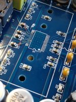
It's 010 which is strange. There's R010 code which is 10mOhms but you would have seen such a low value on DMM even in circuit.
edit: it's actually 01D which indeed is 100K in the EIA-96 system.
Oh! this makes perfect sense, then these have to be the gain resistors 100%.
You're pretty smart!
Gain fix
Hello,
I read quite a bit of threads online and saw that you are very polite and understanding, so i decided to ask you a very common question that i'm sure you answered 100 times.
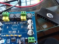
I bought this 2.1 Blutooth board from China and i'm quite pleased with it, but there are some problems.
TPA3116D2 Bluetooth 5.0 2.1 Channel AMP
1) There is an awful hissing sound. I plan on fixing it with reducing the gain to 20dB.
As you can see from the photo i've marked the resistors connected to pin 7 and 8 on the chips. Right now the gain is set to 32dB and the subwoofer chip is set as slave and the L/R ship as master.

My question is: Do i have to change both the master resistors to open+5.6k (as per datasheet Table 1) and the slave resistors to 51k+51k (to set the gain to 20dB too) or only the master chip resistors and leave the subwoofer (slave) chip set to 32dB gain?
2) I found that when the board is near AC power lines there seems to be an audible 'buzz' i dont know if it is fixable, but i'll be using batteries to power it anyways so it doesn't really matter.
Any mods you suggest are welcomed. I have excellent soldering skills and the right equipment so everything is possible 🙂
Thanks for the help and have a wonderful weekend!
Hello,
I read quite a bit of threads online and saw that you are very polite and understanding, so i decided to ask you a very common question that i'm sure you answered 100 times.
I bought this 2.1 Blutooth board from China and i'm quite pleased with it, but there are some problems.
TPA3116D2 Bluetooth 5.0 2.1 Channel AMP
1) There is an awful hissing sound. I plan on fixing it with reducing the gain to 20dB.
As you can see from the photo i've marked the resistors connected to pin 7 and 8 on the chips. Right now the gain is set to 32dB and the subwoofer chip is set as slave and the L/R ship as master.
My question is: Do i have to change both the master resistors to open+5.6k (as per datasheet Table 1) and the slave resistors to 51k+51k (to set the gain to 20dB too) or only the master chip resistors and leave the subwoofer (slave) chip set to 32dB gain?
2) I found that when the board is near AC power lines there seems to be an audible 'buzz' i dont know if it is fixable, but i'll be using batteries to power it anyways so it doesn't really matter.
Any mods you suggest are welcomed. I have excellent soldering skills and the right equipment so everything is possible 🙂
Thanks for the help and have a wonderful weekend!
Yes you'd have to replace both sets of resistors. Changing only the master set will put master at 20dB of gain and slave will remain at 32dB.
I think your board also has a BT chip on it. So it might work the same way as the others with BT onboard. Analog sound goes into the BT chip's ADC, then comes out on its DAC output (for analog line in into the board).
The BT chip would negate (probably) any advantage a separate decent DAC would give you.
Thanks for the quick reply! I'll swap them next week and update.
Any clue what should i do with the 'Bass frequency knob'? Is there a reasonable value i should set it at or it is not very functional?
Any clue what should i do with the 'Bass frequency knob'? Is there a reasonable value i should set it at or it is not very functional?
I don't know what the knobs do as I don't have these types of boards, I have a simple stereo one for left/right on highs and two mono ones for left/right lows. And I'm using an active crossover before them.
@Trileru so I got around setting my amp's gain to 20 dB, but before I do that I tried running the amp with absolutely no gain resistors (open circuit), surprisingly the amp ran fine? and there was almost no audible hiss, makes me wonder what happens If I set no gain resistors, but also how would I know if I have correctly soldered the gain resistors haha.
Depending on your source that may work or not.
Those resistors set the input impedance so it's a good idea to have them to spec for a known good input impedance. You might have issues with frequency response based on the resulting input impedance and the coupling caps values.
Those resistors set the input impedance so it's a good idea to have them to spec for a known good input impedance. You might have issues with frequency response based on the resulting input impedance and the coupling caps values.
Anybody has the same board could tell me where does pin 12 (mute) start? I cant trace it anywhere on any of the resistors.

How many layers are these boards? Specifically the XH-M543. I'm thinking about drilling two holes through the board and threading the heatsink for easy removal/replacement of the heatsink.
you already have 2 holes just tap the heatsink. How many times does someone remove a heatsink?
The new boards don't have any heatsink holes. When the heatsink is glued on removing it once is tough. I can see changing gain and then perhaps doing bootstrap snubbers....etc.
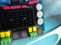
I have played with a bunch of TPA3116 boards. I usually replace the existing heatsink with a larger one and use silicone to glue the heatsink on. A twist on the heatsink breaks the silicone glue very easily.
I am currently playing with another TPA3116 2.1 board. The heatsinks are removed to make changes on the board. It hasn't gone into thermal shutdown yet. Power supply is 22Volts. Sub is 4 ohms.
I am currently playing with another TPA3116 2.1 board. The heatsinks are removed to make changes on the board. It hasn't gone into thermal shutdown yet. Power supply is 22Volts. Sub is 4 ohms.
I have three of these boards.....the last one had a lot of silicone and when I twisted the heatsink I ripped off the chip.
maybe it wasn't silicone. Try a razor blade between the heatsink and the chip, if there is room.
When we had our house built 30 years ago, the plumber used silicone the attach pedestal sinks in 3 bathrooms as well as the soap dishes and towel racks to the walls. I said a lot of bad words when I had to replace the faucets.
When we had our house built 30 years ago, the plumber used silicone the attach pedestal sinks in 3 bathrooms as well as the soap dishes and towel racks to the walls. I said a lot of bad words when I had to replace the faucets.
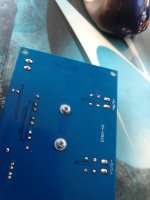
I drilled some holes in the dead board for fun.......there doesn't appear to be any traces in the holes, other than the entire bottom plane of the board appears to be a ground plane. I can insulate the screws..........or perhaps glue on a smaller heatsink that still allows access to the components as you mentioned above.
Attachments
I drilled holes .400" from the centerline of the chip on a good board (same place as the inner hole pattern above) and milled a spotface in the bottom of the board to get the ground plane away from the screw heads. Heatsink was tapped with 2.5mm threads. Amp works fine...no issues.
Attachments
Hi Everyone,
Can someone please suggest me a very cheap below $10 or max $15 class d amplifier board. I have been away from this thread so wanted to know what are the good currently on market.
Thanks,
S
Can someone please suggest me a very cheap below $10 or max $15 class d amplifier board. I have been away from this thread so wanted to know what are the good currently on market.
Thanks,
S
- Home
- Amplifiers
- Class D
- TPA3116D2 Amp