I have set the gain 32dB on same board and I admit the sound quality is the best among all the TPA 3116 , TPA 3118 , TDA 7498 boards I have tried so far (I have tried a dozen of amps). I am looking forward to change input capacitors on these in hope of further improvement. Doesn't 5.6uF should be the right values for this modded board (Gain 32db) as input caps ?I am planning to use Polypropylene Caps.R2/R3 sets the gain of the amp. I think they are 100k/20K on your board. That makes for 26dB gain. Check page 14 of datasheet. You have options for 20dB (lower than now), 26dB which you have now, and louder for 32dB and 36dB. For 32dB you need R2 100K so you don't change that, and R3 39K. So you only replace R3 with 39K for extra 6dB. If you want to go for max 36dB you replace R2 with 75K and R3 with 47K. But input impedance decreases to 9K from 30K which you now have. So you need to up the value of input capacitors C6/C9 to 3.3uF/4.7uF so you don't loose any bass.
Check schematic from page 26 from datasheet, your amp should be the one in the upper part of the schematic. Check the pin numbers and follow the traces to find the parts you want to replace.
Keep in mind that this small board does not have any output filter. I don't see any inductors. They are the 10uH value in the datasheet schematic, with 680nF capacitors to ground. Your board completely misses that, and I wouldn't use it like this. Replacing the input capacitors with same value does almost nothing quality, even if you use 100$ capacitors since you don't have an output filter. That is the best improvement you can do to this board.
With gain set to 32dB input resistance is 15kOhms. A 5.6uF coupling cap results in a 3dB corner frequency of 1,89Hz. Pretty enough imho. Further increasing capacitance will increase any popp on power up/down without contributing to sound quality. Instead of fiddling with "hi-end" caps it may be a better idea to match their capacitance. I found out this can reduce popp considerably.I have set the gain 32dB on same board and I admit the sound quality is the best among all the TPA 3116 , TPA 3118 , TDA 7498 boards I have tried so far (I have tried a dozen of amps). I am looking forward to change input capacitors on these in hope of further improvement. Doesn't 5.6uF should be the right values for this modded board (Gain 32db) as input caps ?I am planning to use Polypropylene Caps.
Last edited:
Ohkay, as for now there is no pop at powering on or switching off.With gain set to 32dB input resistance is 15kOhms. A 5.6uF coupling cap results in a 3dB corner frequency of 1,89Hz. Pretty enough imho. Further increasing capacitance will increase any popp on power up/down without contributing to sound quality. Instead of fiddling with "hi-end" caps it may be a better idea to match their capacitance. I found out this can reduce popp considerably.Ohkay,
Or, preferably, a cheap good one.Buy another cheap /bad Chinese board ?
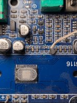
You can try soldering the resistor directly to pin 8 & 9. Though that will make impossible to mount heatsink on the chip. You can try scrapping of the trace which leads to those two pads and solder the resistor across those two points though.@Trileru So I stripped off the soldering pads while trying to solder a 5.6k resistor for the master gain. Any idea where else I could solder the 5.6k resistor?
View attachment 1057243
I have indeed tried scrapping but I did not find the upper traces for some reason, I scrapped and scrapped and only found the bottom one. Which direction should I be aiming for? top left right?You can try soldering the resistor directly to pin 8 & 9. Though that will make impossible to mount heatsink on the chip. You can try scrapping of the trace which leads to those two pads and solder the resistor across those two points though.
Scrap off the traces marked Green, Red & Yellow. If the multimeter shows continuity across Green & Yellow points, you can solder the resistance across Red & Yellow. If it doesn't shows continuity you will have to solder it across Red & Green anyhow.
Attachments
Thank you so much for your advice. I've managed to scrape the traces of Yellow and Red points (they do have continuity) and solder two copper wires from the points to a 5.6k resistor. When the resistor is in circuit, it measures 0 Ohms, and during operation it measures 0 volts, and also measuring the two points without the resistor measures 0 volts. Is that normal?Scrap off the traces marked Green, Red & Yellow. If the multimeter shows continuity across Green & Yellow points, you can solder the resistance across Red & Yellow. If it doesn't shows continuity you will have to solder it across Red & Green anyhow.
Attachments
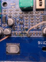
The Resistor used in this position is Gain sensing resistor so I feel its normal to have 0 potential drop across it. If the amp is working okay now then you can simply solder a 1/8 watt 5.6 k resistor directly to those spots (Red & Yellow). Will be much neater that way.Thank you so much for your advice. I've managed to scrape the traces of Yellow and Red points (they do have continuity) and solder two copper wires from the points to a 5.6k resistor. When the resistor is in circuit, it measures 0 Ohms, and during operation it measures 0 volts, and also measuring the two points without the resistor measures 0 volts. Is that normal?

Funny enough the amp worked fine with no gain resistor in place, couldnt hear a difference, how could it be?The Resistor used in this position is Gain sensing resistor so I feel its normal to have 0 potential drop across it. If the amp is working okay now then you can simply solder a 1/8 watt 5.6 k resistor directly to those spots (Red & Yellow). Will be much neater that way.
Also thank you for your efforts!
Thank you for your efforts, I’ve actually just got a shui yang tpa3255, plan on putting it with a Classix II build!Great! Now that you have it working you can finally enjoy music! I myself is using a heavily modded dual TPA 3116 red board and thoroughly enjoying it. TPA 3255 upgrade next.
Great. I myself is tuning my Overnight Sensation TM since last one year in combination to the TPA 3116 board that i have finally settled on. None of the better TPA 3255 boards are available in my country so am eyeing on Aiyima A07 unless Allo releases one anytime soon.Thank you for your efforts, I’ve actually just got a shui yang tpa3255, plan on putting it with a Classix II build!
Hello, I just wanted to share a small hack to reduce the gain of a cheap chinese board with tl074 with minimal modification.
The tl074 use two opamp per channel, the first one in inverter configuration (with a gain of 10db on my board) the second one as buffer.
I added a 1k resistor in parallel with the 20k feedback resistor to lower the gain of the first opamp to -3db (nothing special in this value, I just happened to have two 1k resistor lying on my desk).
I hope this might help if you want to experiment, this modification is not as invasive as changing the resistors under the heat sink or removing the opamp.
I think the gain of 10 is actually 20db at the voltage amplification section isn't it? I was also confused by this because I was thinking about power gain but after researching cyperpit's schematic that showed 20db he is correct.
http://www.sengpielaudio.com/calculator-gainloss.htm
I think your gain is actually negative rather than +3b because the input preamp is inverting and that will make it G = -(.950/2) I think you might want something more like a 3.3k resistor with that method then it would probably give your desired gain of 3. That would be a nice balance.
I also modified the gain on my XH-M543 board by changing R12 and R16 to 10k to make it a 6db gain. I then changed the main gain to 20db. I chose 6db to add with the 20db because I plan to change my XH-M542 boards to be a gain of 26db which is close to the normal 29db I see in home theater given that is my intended application (an outside patio 5.0 surround system). Having the preamp 6db gain followed by 20db makes the 543 a much better match for the 542 mono board.
I changed the input resistor rather than the feedback resistor because the 2k input is a bit low for the 1uf capacitor on the board. I also considered adding a second surface mount cap in parallel with the input coupling cap but I got a good frequency response once I increase the input resistance.
Strangely I also had a board with a bad tl074 opamp (or I somehow shorted it out while modifying it) which took a while to debug and made the process quite frustrating.... Fortunately or unfortunately I had already done some damage to another 435 board so I just stole the opamp from that one (surface mount soldering chips is actually easier than resistors because they don't move as much).
On the xh-m542 board I changed the two resistors to set the gain to 26db. The overall changes to the 543 are about the same given that I only had to solder one resistor back to get the 20db gain and then had to change the two preamp input resistors on the 543 board.
I think the xh-m542 mono boards are better to work with. They have no preamp so it just makes for less to deal with.
-Rich
Last edited:
Decided to try the ZK-502H (one particular reason is that is seems to have the output snubbers in place - did not check, just by the count of the parts near the output inductors)
On bluetooth or wired (on aux) to the phone works perfect. But wired to the PC, it has noise with both internal or external sound card. Running on old laptop brick, 19V, I think it's a Delta power supply. Will try another power supply, this one is grounded and maybe that's an issue since the PC ground is wired to GND
Potentiometer is not to be used at very low levels (cheap one, nothing unexpected)
Not sure about the power switch if played at full power, also output inductors look small-ish
Not sure about the usb power claiming to work as both host (insert stick) and device (connect as soundcard to pc) - don't have an usb-a to usb-a cable in the drawer
Bluetooth is unfortunately SBC only, no sign of any decent audio codec
Hello XProper enclosure for 3116, finally...
I finally mounted some proper banana terminals and RCA input jacks for my TPA3116D2. I am using the direct wire from the 19V laptop brick to the PCB.
Pls. How did you manege to get proper 19V socket on the amp case? I own a YJ V2 board playing very sactirfying till now but the female socket, from a PC board, is getting poor contact. I´m using a generic 19V PC charger from Acer.
TIA
Something like this works well. You have to be careful about the center pin diameter. Sometimes too large or too small.
https://a.co/d/bZhmOQc
https://a.co/d/bZhmOQc
I tried one of these and a lot of features for $5. Not bad for a DIY kitchen radio.Decided to try the ZK-502H (one particular reason is that is seems to have the output snubbers in place - did not check, just by the count of the parts near the output inductors)
On bluetooth or wired (on aux) to the phone works perfect. But wired to the PC, it has noise with both internal or external sound card. Running on old laptop brick, 19V, I think it's a Delta power supply. Will try another power supply, this one is grounded and maybe that's an issue since the PC ground is wired to GND
Potentiometer is not to be used at very low levels (cheap one, nothing unexpected)
Not sure about the power switch if played at full power, also output inductors look small-ish
Not sure about the usb power claiming to work as both host (insert stick) and device (connect as soundcard to pc) - don't have an usb-a to usb-a cable in the drawer
Bluetooth is unfortunately SBC only, no sign of any decent audio codec
View attachment 1067906View attachment 1067907
- Home
- Amplifiers
- Class D
- TPA3116D2 Amp