try to ground the Ground of the signal to chassis.
for psu no grounding. Try that and see
I have 2 of these board stuffed together close each other in pbtl mode with 2 giant 4 amps traffo in one small case and no noise and pops at all. Dead silent and sounds spectacular...
Those smd parts near the input terminal are the anti pop circuit. I once avoid that and make direct connection to the TPA input let and it pops but after using the terminal pops gone...
I've a plastic chassis (3D printed 😛)... so no ground. Could be that?
Furthermore, I use the ampli with my PC. So it happens that, whilst the ampli is always on, the PC and USB card go in stand-by. So, when I wake up the PC, the pops arise. Is there any way to prevent it? Could a "speaker protection board" be of any help?
Another question: is it only me?! 😕😕😕
The pc pops, so everybody that connects a similar pc to any poweramplifier that is on, will hear what you hear. (Related thinking out of the box, I improved dieselconsumption and emissions of my VW TDI by taking bikes, the bikes save fuel and have zero emission. You do hear the wind a little on highway, but that is only slight offer when I do so much good for environment. Bikes were unused standing in garage, so cleans up space in garage too, a real win win)

Modify
Is it anything to mod with this board?
Very dissapointed about the harschness.
Bootsnubber maybe?
But where and what values?
Is it anything to mod with this board?
Very dissapointed about the harschness.
Bootsnubber maybe?
But where and what values?
My suspicions would fall on the opamps being infected with switching noise as the most likely cause of harshness. What are the opamps doing, circuit-wise ? Are they tone controls?
<edit> OK found the schematic on the previous page 🙂
<edit> OK found the schematic on the previous page 🙂
Last edited:
Yeah, me too!
Me too Clengman. I'd like to know what is so horrible about these two boards. Because both the boards sound fine to me!
The red dual chip 3116 board I own had some hiss. So, I always used it with the Guanzo two tube preamp with the volume pot on the amp cranked to maximum. And used the volume pot on the preamp to control the level.
But a friend of mine said to remove dual chip's volume pot and on/off. I replaced the stock volume pot with a 10K stereo one. (Original was 50K which he thinks is a linear, and not an audio pot).
Now the dual chip amp is whisper quiet! And I can use it "stand alone" with no preamp.
As for the blue/black board. Originally I didn't like it much, but gave it a second listen once I got the Guanzo (which people dismiss as well but to me sounds just fine). I think originally I was running the Blue Black with just a straight passive preamp and that just wasn't a right match for it.
There is a page someplace here which has photos of all the amps and what they are known by: blue/black, YJ 2.0, etc. That is helpful.
Mark
I'm definitely interested to know what you found inadequate about these two boards. Thanks!
Me too Clengman. I'd like to know what is so horrible about these two boards. Because both the boards sound fine to me!
The red dual chip 3116 board I own had some hiss. So, I always used it with the Guanzo two tube preamp with the volume pot on the amp cranked to maximum. And used the volume pot on the preamp to control the level.
But a friend of mine said to remove dual chip's volume pot and on/off. I replaced the stock volume pot with a 10K stereo one. (Original was 50K which he thinks is a linear, and not an audio pot).
Now the dual chip amp is whisper quiet! And I can use it "stand alone" with no preamp.
As for the blue/black board. Originally I didn't like it much, but gave it a second listen once I got the Guanzo (which people dismiss as well but to me sounds just fine). I think originally I was running the Blue Black with just a straight passive preamp and that just wasn't a right match for it.
There is a page someplace here which has photos of all the amps and what they are known by: blue/black, YJ 2.0, etc. That is helpful.
Mark
My suspicions would fall on the opamps being infected with switching noise as the most likely cause of harshness. What are the opamps doing, circuit-wise ? Are they tone controls?
<edit> OK found the schematic on the previous page 🙂
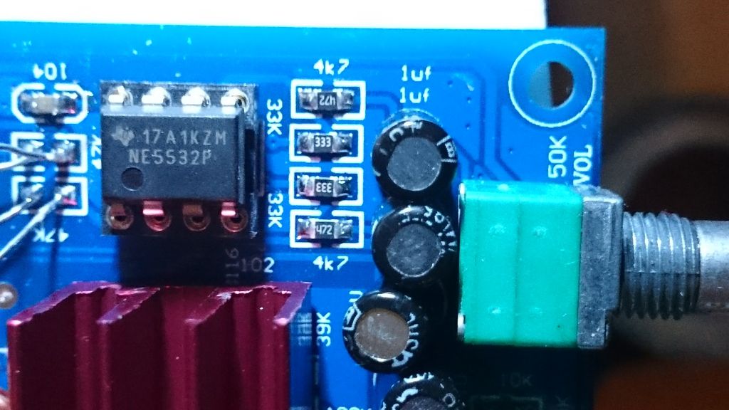
Its NE5532P opamps, don't have anything other to switch to.But you they are so bad?
Opamps aren't bad in and of themselves, just they're a bit tricky to get sounding really good.
In this case I see that there's a master volume control which has been given rather a heavy load caused by the opamp circuit beyond it being inverting. Not sure why they chose that configuration but its not a good one for sound quality. Those 4k7 resistors connected to opamp A really need to be swapped out for 47ks (at the minimum).
In this case I see that there's a master volume control which has been given rather a heavy load caused by the opamp circuit beyond it being inverting. Not sure why they chose that configuration but its not a good one for sound quality. Those 4k7 resistors connected to opamp A really need to be swapped out for 47ks (at the minimum).
Opamps aren't bad in and of themselves, just they're a bit tricky to get sounding really good.
In this case I see that there's a master volume control which has been given rather a heavy load caused by the opamp circuit beyond it being inverting. Not sure why they chose that configuration but its not a good one for sound quality. Those 4k7 resistors connected to opamp A really need to be swapped out for 47ks (at the minimum).
Thanks!
It´s getting better!
Changed 4 resitors to 47k.
I don´t know about these?
Your photo and the schematic don't seem to agree - you're showing 33k resistors but there are none of that value in the schematic. So I'm lost....
The power supplies to the opamps would be the next area to attack but they're not shown on the schematic either.
The power supplies to the opamps would be the next area to attack but they're not shown on the schematic either.
Your photo and the schematic don't seem to agree - you're showing 33k resistors but there are none of that value in the schematic. So I'm lost....
The power supplies to the opamps would be the next area to attack but they're not shown on the schematic either.
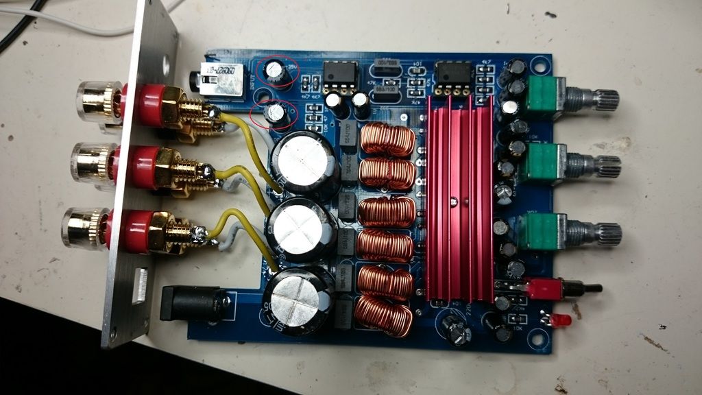
Could it be these in red?
100uF/35v
Those to right is 1uF.
I've a plastic chassis (3D printed 😛)... so no ground. Could be that?
Furthermore, I use the ampli with my PC. So it happens that, whilst the ampli is always on, the PC and USB card go in stand-by. So, when I wake up the PC, the pops arise. Is there any way to prevent it? Could a "speaker protection board" be of any help?
Another question: is it only me?! 😕😕😕
Are you having troubles regarding 'pop' or noise/hum from the boards ?
IMHO PC doesn't cause any interference. Like what I did, I run an output direct from my PC to the TPA and it just dead quiet with my 83dB speaker.
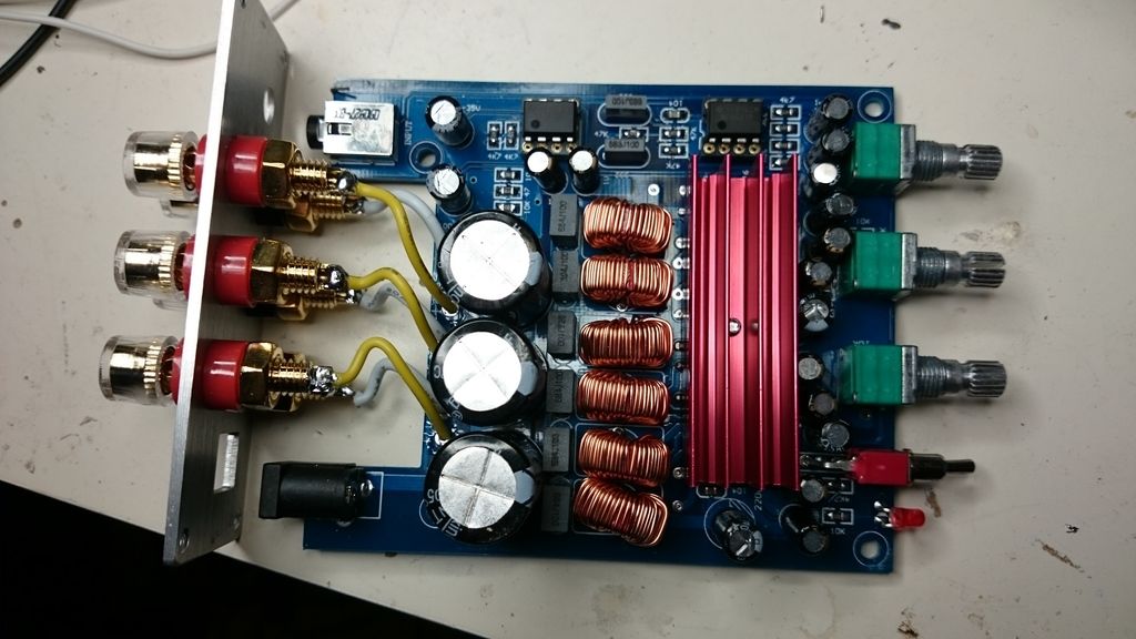
Maybe a photo description of the board wiring inside the case would make clear picture.
Thanks!
It´s getting better!
Changed 4 resitors to 47k.
I don´t know about these?
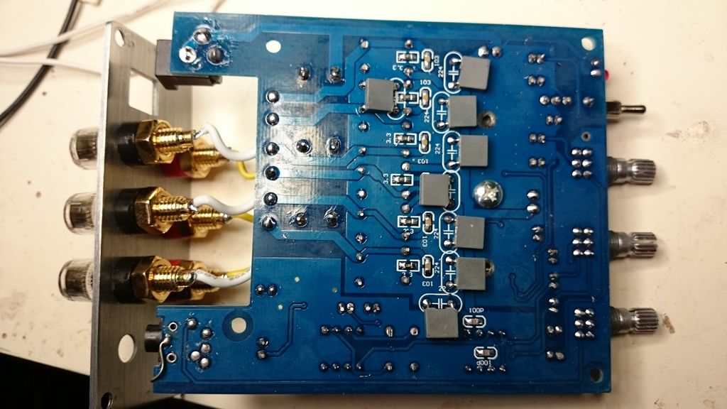
This board is very similar to mine albeit with different values. To the right of the op-amp on the right ... The 4K7 and 33K resistors in conjunction with the 1uf decoupling caps (on the input after the volume control) and the 100pf caps on the underside of the board implement an inverting audio frequency bandpass filter at 34hz and 48Khz. Unfortunately this filter is only on the ".1" portion of the board.
The two 4K7 resistors you show replaced with 47K are resistors is the ".1" channels LP filter. That Fc of that filter frequency has now be reduced 10x from the previous Fc. I can't read the two black cap values that determine the filter's Fc with the original 4K7 resistors (my board used 10K resistors and .22uf/.1uf to implement a 107hz 2nd order Butterworth LP filter). You don't show the other two 4K7 resistors that you indicated you swapped for 47K. If they are to the left of the left op-amp, they are simply buffer resistors between the final op-amp stages and the TPA3116 input. I believe my board is running the TPA3116 at 26db gain. That would specify the input impedance to the TPA 3116 at 30K ohms (TI spec). So you may have reduced the signal going into the chip with the higher resistor value.
If you replaced the 4K7 resistors next to the 33K resistors on the right with 47K, you've changed the lower Fc of the ".1" channel's audio bandpass filter from 34hz to 3.4hz (that would correct the problem others have had on the missing low end frequencies on the sub channel). I use that filter "as-is" to mitigate X-max issues on my sub at high power).
You say it sounds better ... but if my analysis is correct, you've only modified the ".1" channel and I presume the harshness you mention is on the L-R channels as the ".1" channel doesn't produce any high frequencies. Having said (all) that, perhaps abraxalito's comment on the 4K7 resistors (rightmost ones) has an impact on the overall sound that I do not understand ... their effect on the op-amp circuit nor how it would effect the L-R channels.
Lastly, my board is dead quiet. No turn-on, turn-off pops whether using the boards switch or just plugging in the PS to the DC jack. I have no pop issues starting/pausing/restarting media player on my PC (nor playing mp3s on my phone). Never used it having the PC come out of hibernate so that may be the issue.
I am keenly interested on abraxalito's take on my post.
Last edited:
This board is very similar to mine albeit with different values. To the right of the op-amp on the right ... The 4K7 and 33K resistors in conjunction with the 1uf decoupling caps (on the input after the volume control) and the 100pf caps on the underside of the board implement an inverting audio frequency bandpass filter at 34hz and 48Khz. Unfortunately this filter is only on the ".1" portion of the board.
The two 4K7 resistors you show replaced with 47K are resistors is the ".1" channels LP filter. That Fc of that filter frequency has now be reduced 10x from the previous Fc. I can't read the two black cap values that determine the filter's Fc with the original 4K7 resistors (my board used 10K resistors and .22uf/.1uf to implement a 107hz 2nd order Butterworth LP filter). You don't show the other two 4K7 resistors that you indicated you swapped for 47K. If they are to the left of the left op-amp, they are simply buffer resistors between the final op-amp stages and the TPA3116 input. If you replaced the 4K7 resistors next to the 33K resistors on the right with 47K, you've changed the lower Fc of the ".1" channel's audio bandpass filter from 34hz to 3.4hz (that would correct the problem others have had on the missing low end frequencies on the sub channel). I use that filter "as-is" to mitigate X-max issues on my sub at high power).
You say it sounds better ... but if my analysis is correct, you've only modified the ".1" channel and I presume the harshness you mention is on the L-R channels as the ".1" channel doesn't produce any high frequencies. Having said (all) that, perhaps abraxalito's comment on the 4K7 resistors (rightmost ones) has an impact on the overall sound that I do not understand ... their effect on the op-amp circuit nor how it would effect the L-R channels.
Lastly, my board is dead quiet. No turn-on, turn-off pops whether using the boards switch or just plugging in the PS to the DC jack. I have no pop issues starting/pausing/restarting media player on my PC (nor playing mp3s on my phone). Never used it having the PC come out of hibernate so that may be the issue.
I am keenly interested on abraxalito's take on my post.
My boards subchannel I think is just that, no x-over what I can hear, only can control volume with the middle knob.Seems to be variants of this board with x-over.
Maybe just placebo my change of resistors but somehow it feels a little better in the harchness, not as good as my tripath but better.
My boards subchannel I think is just that, no x-over what I can hear, only can control volume with the middle knob.Seems to be variants of this board with x-over.
Maybe just placebo my change of resistors but somehow it feels a little better in the harchness, not as good as my tripath but better.
Yes, the middle knob is only a volume control. It does not alter the sub's x-over frequency. The sub's x-over is fixed by the values of two resistors and two capacitors. What are values of the two black capacitors between the op-amps (can't read there markings in the pic).
Do you have a driver hooked up to the sub channel? If so, is it producing frequencies high frequency audio (>1Khz)? If so, then there is an error with your board's design/implementation.
Lastly, I am having a fairly good experience with my board. Perhaps my limited hearing (nothing over 2Khz) spares me from any deficiencies it might have. Hence, I needed my GF to help me "voice" the crossover between my sub channel (now modified to a 876hz linkwitz-riley LP filter) and my L-R channel drivers.
Since you seem very capable of modifying your board, I can determine values if you want to change the sub xover frequency (assuming its working correctly).
Last edited:
Yes, the middle knob is only a volume control. It does not alter the sub's x-over frequency. The sub's x-over is fixed by the values of two resistors and two capacitors. What are values of the two black capacitors between the op-amps (can't read there markings in the pic).
Do you have a driver hooked up to the sub channel? If so, is it producing frequencies high frequency audio (>1Khz)? If so, then there is an error with your board's design/implementation.
Lastly, I am having a fairly good experience with my board. Perhaps my limited hearing (nothing over 2Khz) spares me from any deficiencies it might have. Hence, I needed my GF to help me "voice" the crossover between my sub channel (now modified to a 876hz linkwitz-riley LP filter) and my L-R channel drivers.
Since you seem very capable of modifying your board, I can determine values if you want to change the sub xover frequency (assuming its working correctly).
Those two capacitors are 1uF.
Just did a dirty messure and it´s to high for me.
The cross should be 80hz or even lower and I asume its first order cross.
Not so useful.
I can solder but not much more than that...🙂
I believe I am trying to do exactly what he did. The fundamental goal here is to use the balanced inputs of the tpa3116 chip. Doing unbalanced to balanced conversion, as well as DC-blocking and input isloation, is a typical application of 1:1 line-level transformers.
Now, am I doing it right? That's open to debate. 😕
When I said he left ground open, I was specifically referring to the input signal ground. Ultimately I guess all grounds are the same, so I think we're both right. But my point was that the connection on his amp board where the RCA ground typically goes he didn't explicitly connect it to anything... but yes, that input ground implicitly ties into the board ground, which in turn connects to the standoffs, which in turn connect to the chassis, which is tied to earth.
I am doing something similar, in that my input signal ground is "open", i.e., I didn't explicitly tie it to anything. But my DMM says the input ground is implicitly tied to the DC ground. I don't have a true earth in my chassis, since the PSU is in a separate box, so I'm guessing DC 0V will have to suffice for ground.
Anyway. I made some progress on the hum issue. That was by putting a jumper between pins 2 and 3 (CT and input NEG, respectively) on the primary side of the transformer. At least this fixed the hum on my low-sensitivity test speakers.
I took the rig to my other speakers, turned in on, hum still there. In this arrangement, I had the Astron power supply sitting on top of the amp chassis. Thinking maybe my jumpers came loose, I moved the PSU off the amp chassis so I could remove the amp's top cover. I checked my jumpers, they still looked good. I left the PSU off to the side, powered it back up, and the hum was gone. Wha?! So I put the Astron back on top of the amp chassis, and the hum came back.
So it appears the Astron SL-11R power supply leaks some kind of EMI? Also, just now I realized that the PSU itself has a very slight hum when powered on.
The natural question then is, was the hum fixed by the jumper or simply by moving the power supply? The answer is both. I just now pulled the jumper with the amp connected to the more sensitive speakers and the Astron moved away. Hum is back. Re-applying the jumper (and leaving the PSU aside) kills the hum.
I do get a weird noise (yet another kind of hum) in one speaker when the attenuator is all the way up, but I assume that's a problem with the attenuator... if I start using this amp in that manner, I'll just remove the attenuator outright.
So anyway, final config (for now😉) is like this:
Transformer Pri Pin 1 / input+ = RCA POS
Transformer Pri Pin 2 / CT = jumper to Pin 3
Transformer Pri Pin 3 / input- = RCA GND
Transformer Sec Pin 5 / output- = amp signal input-
Transformer Sec Pin 6 / CT = couple to amp signal input gnd via 1uF cap
Transformer Sec Pin 7 / output+ = amp signal input+
Hi Matt, sorry for the radio silence.
I've not read all recent posts but thought I'd mention the following, in case this helps.
I always drive my amp (with input transformers) from a low impedance source. If you have a potentiometer (volume control) prior to the transformer primary, then the impedance of the source driving the transformer is probably high and varying with volume level. This will cause issues (noise, hum) with many input transformers. You can test this by cutting out the volume control and driving the input transformer directly from a low impedance source (a laptop headphone output would be fine for testing, with volume controlled in the digital domain).
Don't 'short' or leave open any section of the transformer primary. It sounds like you've connected the signal of your unbalanced source to the transformer primary + connection, ground to the CT and then played with having the primary - connection floating or tied to CT. Try connecting the source signal to the transformer primary + connection and source ground to the transformer primary - connection, so the whole primary coil is in series with the source.
You're correct that I've never connected the secondary CT to amp input ground, as I was concerned that this would provide a route to ground for the amp input bias voltage. I didn't have any problems with my amp board and transformer with this approach. Remember that the input signals will be connected to amp input ground anyway, as the amp inputs have an impedance to ground.
Good luck 🙂
The two 4K7 resistors you show replaced with 47K are resistors is the ".1" channels LP filter. That Fc of that filter frequency has now be reduced 10x from the previous Fc.
Good point - to preserve the same Fc, the input caps (C1,2 in the schematic you posted) should be reduced by a factor of 10, to 100nF.
You don't show the other two 4K7 resistors that you indicated you swapped for 47K.
The ones I intended be swapped were the feedback resistors (R2,3) to preserve unity gain.
If you replaced the 4K7 resistors next to the 33K resistors on the right with 47K, you've changed the lower Fc of the ".1" channel's audio bandpass filter from 34hz to 3.4hz (that would correct the problem others have had on the missing low end frequencies on the sub channel). I use that filter "as-is" to mitigate X-max issues on my sub at high power).
Which resistors on your schematic do the 33ks correspond to?
You say it sounds better ... but if my analysis is correct, you've only modified the ".1" channel and I presume the harshness you mention is on the L-R channels as the ".1" channel doesn't produce any high frequencies. Having said (all) that, perhaps abraxalito's comment on the 4K7 resistors (rightmost ones) has an impact on the overall sound that I do not understand ... their effect on the op-amp circuit nor how it would effect the L-R channels.
Your analysis seems to me to be correct. The idea behind my suggestion was that harshness comes about from noisy power supplies (in general) and the 4k7s put a load on the power supply of whatever is driving this amp. A heavy load induces harshness in the source component, via its power supplies.
I am keenly interested on abraxalito's take on my post.
More than happy to oblige 🙂
Could it be these in red?
100uF/35v
Those caps could be the decouplers for the opamp supplies, yes. In which case they could contribute to the harshness by coupling noise from the two power rails (+ and -) into your GND. Whether they do in fact do that depends on the layout of the GND connections.
You could experiment by removing both and putting in an extra wire from the centre point of the pair - in essence a dedicated GND. You do this by leaving the cap connections to opamp pins 4 (-ve supply) and 8 (+ve supply) in place but don't restore the pin on each cap to the GND connection. Instead connect the two cap pins that were formerly going to GND together, then from that junction wire a GND connection to a suitable spot. Hard to determine what the best GND point to attach to without a more comprehensive schematic - you can experiment for best sound.
Those two capacitors are 1uF.
Just did a dirty messure and it´s to high for me.
The cross should be 80hz or even lower and I asume its first order cross.
Not so useful.
I can solder but not much more than that...🙂
Oh, sorry, I meant the rectangular polyester black caps, not the round cans. The 1uf cans are simply bias resistors between op-amp stages (to mitigate any DC offset). The two polyester caps are the caps that determine Fc of the LP filter.
BTW: the two 4k7 resistors that you replace in the photo, one is in the LP filter circuit, the other is a DC bias resistor for the Op-amps.
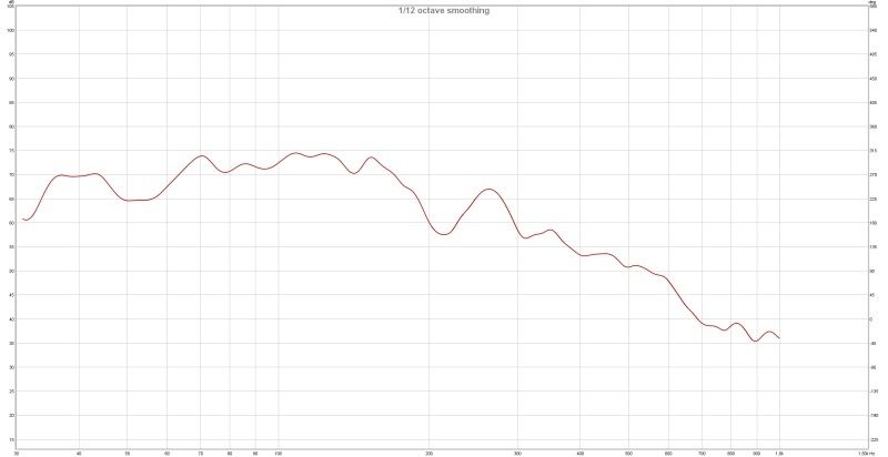
The graph shows the LP with an Fc currently between 200 and 300 hz. I presume this is post your resistor modifications.
Can you take a photo, much like above, but showing both op-amps and the all 4 resistors you replaced?
Last edited:
Which resistors on your schematic do the 33ks correspond to?
The 33K resistors correspond to the 22K resistors on my schematic (R2,R3). Here's my full schematic and my legend. From the pic.'s it appears the amps are the same basic design.
Your analysis seems to me to be correct. The idea behind my suggestion was that harshness comes about from noisy power supplies (in general) and the 4k7s put a load on the power supply of whatever is driving this amp. A heavy load induces harshness in the source component, via its power supplies.
Well this is an area I'm not well versed in. But this is a single DC supply amp. So all the signals are biased up from ground to allow ac waveforms while the op-amps are powered by DC+ and ground. One would think the bias is 1/2 the DC supply voltage as the signal decoupling caps will bias the ac waveform symmetrically.
More than happy to oblige 🙂
Thanks.
- Home
- Amplifiers
- Class D
- TPA3116D2 Amp