Yes, it looks about the same **** I have.
How does it sound on vocal?
I couldn't honestly say. For several (and possibly comically reasons). I have a 2.1 setup with a Scan-Speak w22-4534G (8", 4ohm) "Discovery Woofer" and two Gold Wood 65/4 sealed back mid-high ranges.
First, and most importantly, I can't here much above 1Khz.
Then there's the rising response of the woofer starting at 1khz on up to 3Khz where it breaks up on the graph.
So I'm trying to add to the active LP in the amp (876hz) with a passive 1st or 2nd order filter to further push down the rising response of the woofer. During my experiments, I can ""hear"" a difference in the mid vocals and can alter them high or low. Now I just need other people to tell me which combo sounds the best due to my hearing limitations.
But as I stated before, the L-R channel measures mostly flat from 100hz on up. But that's at 4 ohms. 8 ohm speakers can change things based on the boards inductor values.
Are you using a passive woofer or just stereo speakers? As for the really upper end, I can't hear that stuff at all. Can't recall what others have said about that at the moment.
Last edited:
That's a lot of good information all in one place! Thanks!
This board does not look at all familiar to me though. Is it for sale anywhere currently?
I bought mine here, it should arrive soon.
YJ Assembled TPA3116 Class D Amplifier Board 50W 50W Green PCB | eBay
BR
Eric
I bought mine here, it should arrive soon.
YJ Assembled TPA3116 Class D Amplifier Board 50W 50W Green PCB | eBay
BR
Eric
Thanks!
Last edited:
Hello -
I posted the following on another web forum. Would be interested in any responses members here may have. The "twin-chip board" referred to is this one: 2 100W TPA3116 D2 Dual Channel Digital Audio Amplifier Board 12V 24V for Arduino | eBay
------------------
I just conducted an interesting, and frankly, disappointing, comparison of the twin-chip board and two traditional stereo systems. The setup was as follows:
Front room:
Yamaha home theater receiver, Polk RTi6 speakers
Middle room:
twin-chip board amp, no preamp, Polk RTi4 speakers
Back room:
Marantz 1090 integrated amp (original/unrestored/not re-capped), Cambridge Soundworks Model 6 speakers
Sources for all three: Chromecast Audio units configured as a group, playing Google Play Music. High Dynamic Range "on" on all three CCAs. Yamaha and Marantz were playing with the tone controls at their detents; loudness off; Yamaha set to straight two channel playback with no DSP stuff.
So I was able to walk from room to room to room, listening to the same track and doing essentially instantaneous comparisons.
What was immediately obvious was that the twin-chip board seems to have a very rolled-off top end. Cymbals lack sizzle; snare drums thud instead of snap; strummed acoustic guitars are dull. The Yamaha system was a little brighter than the Marantz, but the twin chip was way duller than both of them -- not at all a subtle difference. I'm 55, not deaf but don't have golden ears.
I had no dog in this fight; I've been pretty impressed with the twin-chip amp up to this point; and I only set this test up because I just took delivery of CCA nos. 2 and 3 and wanted to try out the group-play feature.
Since I have two boxed-up twin-chip boards, I tried them both (with different sets of speaker wire); I also used two different power bricks, one 12 volt/4 amp, the other 19 volt/3.4 amp; no difference in the top end that I could hear.
I guess to rule out an issue with the RTi4 speakers, I should have switched them into one of the other systems. But I'm pretty sure the two Polk models use the same tweeters.
I'd be curious whether anyone else can confirm my impressions, and/or if anyone has thoughts about whether something about the twin-chip's component selection, board layout, or other aspects may be responsible for the lack of top end.
...
Hers a rough schematic ... It's easier to read if you download it to your PC and open with Windows photo Viewer or similar app.
View attachment 530355
...
C23, R8 not correct connections.
If this is single supply then there needs to be a resistor to Vcc and a cap to bypass "bias point" to GND.
If +/- supplies then just GND the +inputs.
edit: OOPS...did not pay attention to the "rough schematic" part soon enough.
🙂
Last edited:
I've observed (and read many comments about) that whenever a (relatively) high impedance is seen by the input of these chip there seems to be "noise" pickup.
In your case the transformers themselves may be the culprit.
Are the cores of the transformers grounded to the board ground?
Do the secondaries have a CT that could be AC coupled to board ground?
There may be hope. 🙂
There is definitely hope! I spent some time just now with a paperclip, jumpering various things together to see if I could get rid of the whine/squeal/squelch. What I found was that the noise went away if I shorted the RCA ground on the transformer input (primary) side to the center tap of the transformer output (secondary) side. The transformer output side center tap in turn connects to the signal ground on the amp PCB.
Also, FWIW, I tried shorting the secondary center tap/signal ground to power ground, that didn't do anything. Also on the secondary side, I tried shorting the center tap/signal ground to the negative signal side: again, no change.
Per your specific questions: Are the cores of the transformers grounded to the board ground? Not currently. Do the secondaries have a CT that could be AC coupled to board ground? Yes, definitely. What ground point on the board do you suggest for this? And how do I AC couple ground? I assume you don't mean a straight short, perhaps a cap? If so, what value?
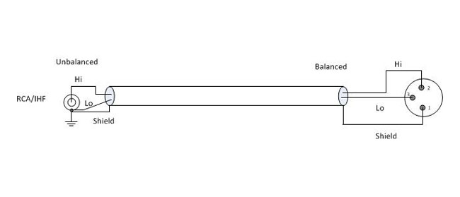
Check out the attached image below, it's Figure 2 from Rane: Sound System Interconnection. If I'm reading it right, it says XLR pin 1 (i.e. signal ground) should be shorted to chassis, and in turn the chassis is earth grounded. Doctormord hinted at this above... but (1) I did try shorting signal ground to the chassis, and it did nothing for the squelch, and (2) my chassis isn't earth grounded, because the mains power supply is in a separate box.
Thanks again everyone!
Attachments

Matt - since you have removed the input coupling caps, you mustn't provide a DC path back to signal ground through your trafos. This means your CT should not connect to signal ground directly, but only through a cap. I suggest 1uF.
What's surprising is you getting any sound at all if the inputs are at signal ground DC-wise.
What's surprising is you getting any sound at all if the inputs are at signal ground DC-wise.
Hey, I have in my hands a Dr Mord 3132 amp board. It sounds amazing. It is essentially a 3116 in a smaller package. It is a beautiful thing. You can experiment with asian type boards if you are into doing mods. Or, if you want something that works perfectly out of the box you can get european quality for a few bucks more.
I have yet to A/B it to my Peter Daniels gain clone kit amp but I suspect the young gun has the edge. I will do this on the weekend.
I tried it with several power supplies. The two laptop bricks I tried were the 19 volt 3 amp type. Both had unacceptable noise. Then i tried a class 2, 12 volt, one amp. It is totally quiet and sounds very good. Then I tried a I.T.E. 24 volt, one amp. Very good. Dead quiet.
I like this one the best so far. It's designed by a company called CUI. They make all kinds of power supplies for medical use. They are available through Digikey. This is the
CUI website Power Solutions | Power Supplies | CUI Inc
I have no vested interest in the company. I just happened to have one of their walwarts in my box of P/S.
Thanks to Dr Mord I have many hours of good listening ahead.
TPA3132D2 - minimum 50 50W class-D amplifier (TPA3116, TPA3118) - #360customs
Thanks j.leger for the review and impressions, really appreciate. 🙂
The boards are made on request and come fully populated/soldered and tested (24h burn-in).
Of course things like headers and pot can be left unpopulated but I wouldn't recommend anything else than Phoenix connectors at the output.
For a quote check pm.
The boards are made on request and come fully populated/soldered and tested (24h burn-in).
Of course things like headers and pot can be left unpopulated but I wouldn't recommend anything else than Phoenix connectors at the output.
For a quote check pm.
Matt - since you have removed the input coupling caps, you mustn't provide a DC path back to signal ground through your trafos. This means your CT should not connect to signal ground directly, but only through a cap. I suggest 1uF.
With this tip, I made a little more progress. Two more ways I found that the squelching is gone: (1) leave the amp board signal ground completely open (i.e. no connection to anything), and (2) do as Abraxalito suggests, and connect amp board signal ground to the transformer secondary center tap via 1uF capacitor.
What's surprising is you getting any sound at all if the inputs are at signal ground DC-wise.
Dunno! Something could very well be sub-optimal here...
I don't think you can generalize that all Asian boards are not good or cannot be as good as a European board.
I have a Dr Mord board too but haven't had the time to assemble it yet. Looking forward to the day I get it running.
I will say that my latest experience with the Sanwu blue PBTL 3118 has been excellent. It is extremely small and I think small with good layout and decent components make a good class D amp. The bypass caps cannot physically be placed any closer and the wire traces from amp to inductor is very short for reduced stray RF. It runs on the warm side but is very quiet and one of the best TPA amps I have heard.
http://www.diyaudio.com/forums/class-d/219730-tpa3118d2-25.html#post4585203
Last edited:
I don't think you can generalize that all Asian boards are not good or cannot be as good as a European board.
I have a Dr Mord board too but haven't had the time to assemble it yet. Looking forward to the day I get it running.
You should do. 🙂
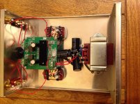
On the transformers... waaaaay back in this thread, in post #3696, Sharpi31 posted a picture of his tpa3116 implementation using Lundahl LL1540 transformers for unbalanced to balanced conversion. Later, in post #3718 he posted a schematic of how he wired the transformer. His schematic is basically straight from the Lundahl LL1540 datasheet. I reproduced Sharpi's pictures below, but there is a fair amount of discussion about transformers that takes place, though much of it is over my head.
Interesting is that he has a 1nF cap and 22k resistor in series between input POS and input NEG (on the amp side). This is per the LL1540 datasheet's suggestion. Also per the datasheet are some jumpers on either side of the transformer... From his picture, it looks to me like he's leaving amp input GND open.
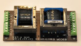
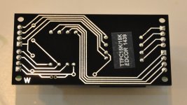
Edcor doesn't document what pins 8 and 4 are on their transformers. I'm trying to get a datasheet and/or some application note document from them. I don't know why these aren't readily available on their website. If you look closely at the pics of the Edcor PCBs, they left holes for R1, C1, and JMP1... I would think a document would explain when and why one might want to use those.
At any rate, I'm thinking the implementation of these two transformers ought to be similar?
Interesting is that he has a 1nF cap and 22k resistor in series between input POS and input NEG (on the amp side). This is per the LL1540 datasheet's suggestion. Also per the datasheet are some jumpers on either side of the transformer... From his picture, it looks to me like he's leaving amp input GND open.
Edcor doesn't document what pins 8 and 4 are on their transformers. I'm trying to get a datasheet and/or some application note document from them. I don't know why these aren't readily available on their website. If you look closely at the pics of the Edcor PCBs, they left holes for R1, C1, and JMP1... I would think a document would explain when and why one might want to use those.
At any rate, I'm thinking the implementation of these two transformers ought to be similar?
Attachments


In this thread there has been discussion about ac1308 standoff holes not being isolated and chipfailures because of that in combination with smps. So sharpie31 ampboard gnd is chassis I think. He did mention noise, could be same amount you find annoying.
edit: maybe this is very wrong, but it looks like source chassis/gnd could be connected to amp gnd chassis, just like it is connected through pin 1 when source and amp use xlr ??
edit: maybe this is very wrong, but it looks like source chassis/gnd could be connected to amp gnd chassis, just like it is connected through pin 1 when source and amp use xlr ??
Last edited:
In this thread there has been discussion about ac1308 standoff holes not being isolated and chipfailures because of that in combination with smps. So sharpie31 ampboard gnd is chassis I think. He did mention noise, could be same amount you find annoying.
About the hum, in post #3696, he says, "no hum from speakers, just slight hiss with my ear to the driver (as good as I've had from any amp)". This is the same post where he provided the picture of his implementation. So I'm pretty sure he's not getting any noise.
This is what he says about his amp board/chassis grounding, from post #3707:
One slightly odd thing about the Audiobah board is that the ground plane on the bottom of the PCB extends to each mounting hole. I used brass PCB pillars so the amp board ground is connected to the chassis at four points. Incoming mains earth is tied directly to the chassis via one of the power transformer fixings. I haven't added any wires linking mains earth to PSU ground, but there doesn't seem to be any problem with this connection coming via the aluminium chassis and brass PCB pillars (I know this isn't best practice though). My approach was to wire things up this way and then review the scheme, if hum etc. we're an issue. The incoming signal and ground are only connected to the Lundahl transformer primary, so isolated from the amp. The Lundahl datasheet suggests that the centre tap of the secondaries should be tied to ground, but I've left this floating given the 3V bias of the amp signal inputs.
edit: maybe this is very wrong, but it looks like source chassis/gnd could be connected to amp gnd chassis, just like it is connected through pin 1 when source and amp use xlr ??

That picture is missing the transformer. 🙂 Go back a page to post #8825, I posted a schematic similar to yours but with a transformer. That one shows balanced ground being tied to earth. Unbalanced ground is explicitly not tied to earth. But Sharpi seems to have good result leaving signal ground open, and in my case, that cures the whining. But putting the cap between the transformer center tap and signal ground also works without whine, so I'm not sure if one is better than the other.
YJ Black/Blue TPA3116d2 snags!
I have a pair of these boards, I have modified these to run PBTL, amongst the mods I have performed the following:
* Panasonic Oscons 330uf Caps x 2 replaced no-name brand
* Installed Wima 1uf Input Coupling Caps
* Removed R1
* Replaced R2 with 5.6k .5 watt Resistor
* Now running 20db gain
* Installed 4 x Coilcraft SER2915L-103 Inductors
I have (twice!) attempted to implement the Bootstrap Snubber mod using Kemet 220NF /100v Caps and 10ohm .5 watt Resistrors to ground, every time I set this up I power-up and the 10ohm Resistors burn-up!
Is this something to do with the board set up PBTL /Mono?
Can't seem to figure out what's going on here???
Any suggestions?
Thx, OW
C23, R8 not correct connections.
If this is single supply then there needs to be a resistor to Vcc and a cap to bypass "bias point" to GND.
If +/- supplies then just GND the +inputs.
edit: OOPS...did not pay attention to the "rough schematic" part soon enough.
🙂
It is a single supply as are all TPA3116. There may be a resistor & Cap somewhere else, I was only interested in the signal path.
Why do think there is a problem with C23 and R8?
What was immediately obvious was that the twin-chip board seems to have a very rolled-off top end. Cymbals lack sizzle; snare drums thud instead of snap; strummed acoustic guitars are dull. The Yamaha system was a little brighter than the Marantz, but the twin chip was way duller than both of them -- not at all a subtle difference. I'm 55, not deaf but don't have golden ears.
I had no dog in this fight; I've been pretty impressed with the twin-chip amp up to this point; and I only set this test up because I just took delivery of CCA nos. 2 and 3 and wanted to try out the group-play feature.
Since I have two boxed-up twin-chip boards, I tried them both (with different sets of speaker wire); I also used two different power bricks, one 12 volt/4 amp, the other 19 volt/3.4 amp; no difference in the top end that I could hear.
I measured the L-R channels of the 2.1 TPA3116 amp I'm using (see post #8818). The L-R take in the signal via the master volume, then to the L-R volume then to 1uf coupling caps and on to the chip.
My measurements show its flat from 100hz until a roll-off starting at 3Khz on up to 10Khz where it's down -3db. I didn't measure beyond 10Khz as I can't hear much above 2Khz. But the bass is kicking -🙂
- Home
- Amplifiers
- Class D
- TPA3116D2 Amp