Missed post🙂Hi irribeo,
what do you use to glue the heatsink back to the TPA 3116 after you have cut it smaller size??
I didn't cut heatsink, overall H,W,D all remain the same. Where heatsink doesn't touch tpa3116 I reduced height. I use some very thin 3M double sided tape, Original YJ used some silicon flexible when dry glue. Don't have heatsinks on 3116 very often.
Back to the more easily achievable targets: Back in July I tried to measure TAS5756 pbtl layout instructions in datasheet, TI notes these are maximum distances in example layouts for powersupply decoupling, from mid solderpoint capacitor to chippin: max 2.5mm for 0.1uF, max ~6mm for 1uF, max ~7mm for 22uF and 10 to 12.5mm for 390uF.
They skipped 1nF for this chip that is a little more sophisticated than tpa I think and chip includes an amplifierpart that probably is very similar to 3118.
They skipped 1nF for this chip that is a little more sophisticated than tpa I think and chip includes an amplifierpart that probably is very similar to 3118.
The TI board isn't poorly designed at all. It's just designed to present a solution that passes EMI testing and provides an attractive BOM while still providing pretty decent audio perfomance.Don't mean to argue for the sake of arguing, But are you implying that TI designed the chip and yet purposedly placed the chip in a poorly designed board to showcase its utility? I am asking a genuine question here, splease do not get me wrong.
Regards,
If the goal is to achieve the best audio performance you possibly can, you can optimize a few things:
(1) Filling the aforementioned "hole" in the power supply decoupling. Plotting an impedance vs frequency curve for the three caps used does show a peak around the amp switching frequency, which can be filled in without too much difficulty. Though you're using big MLCC's, small case polymer caps, etc... to do the job, which will raise the BOM.
How much of a difference this ultimately makes might be small, the TPA itself has pretty good PSRR in the datasheet up to 20KHz... but having a more solid PVCC rail certainly can't hurt anything.
(2) Output capacitors are X7R MLCC. Does the job and cheap, however capacitance/voltage effect can introduce nonlinearity at high signal levels that push the voltage level up. Film caps are ideal for this job, though again, higher BOM cost to use those.
(3) Output inductors droop in value with increasing current, also introducing potential nonlinearity at high signal levels. Changing them for ones with a flatter inductance/current curve would be an improvement, but you're no longer buying a cheap commodity 10uH 'buck regulator' inductor so again, BOM will go up.
For something like an audio amp design for a TV set, the EVM design is excellent as-is. For us weirdos, yeah, maybe we'll want something different.
So where can we find the ideal BOM?The TI board isn't poorly designed at all. It's just designed to present a solution that passes EMI testing and provides an attractive BOM while still providing pretty decent audio perfomance.
If the goal is to achieve the best audio performance you possibly can, you can optimize a few things:
(1) Filling the aforementioned "hole" in the power supply decoupling. Plotting an impedance vs frequency curve for the three caps used does show a peak around the amp switching frequency, which can be filled in without too much difficulty. Though you're using big MLCC's, small case polymer caps, etc... to do the job, which will raise the BOM.
How much of a difference this ultimately makes might be small, the TPA itself has pretty good PSRR in the datasheet up to 20KHz... but having a more solid PVCC rail certainly can't hurt anything.
(2) Output capacitors are X7R MLCC. Does the job and cheap, however capacitance/voltage effect can introduce nonlinearity at high signal levels that push the voltage level up. Film caps are ideal for this job, though again, higher BOM cost to use those.
(3) Output inductors droop in value with increasing current, also introducing potential nonlinearity at high signal levels. Changing them for ones with a flatter inductance/current curve would be an improvement, but you're no longer buying a cheap commodity 10uH 'buck regulator' inductor so again, BOM will go up.
For something like an audio amp design for a TV set, the EVM design is excellent as-is. For us weirdos, yeah, maybe we'll want something different.
I think the WIKI is not up to date.
+1So where can we find the ideal BOM?
I think the WIKI is not up to date.
Is there a consensus on the ideal BOM? Or even a consensus on the ideal PCB to start with? Or are we talking about the hypothetical, as-of-yet-not-available ideal PCB?
Also, I did a quick scan on ebay last night for "tpa3116" and found a couple PCBs that I don't recall ever seeing mentioned in this thread. I'll add a bunch of extra info since ebay links tend to be ephemeral:
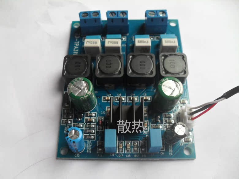
(1) Item 221606115565. Title "1xTPA3116D2 2.0CH Class D 50w+50w beyond TA2024 Digital power amplifier board". Seller xinshuoyisz. Price $16.04 USD w/free shipping from China. Dimensions: 71x46mm. Blue-ish PCB with three blue terminals on one end for speaker outs and DC in. Signal input is one of those three-pin connectors like YJBlue uses. Board is labeled "ZD-TPA3116". Four black inductors, and a smallish 4-fin black heatsink.
A picture, for as long as this link is valid:
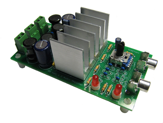
(2) Found via ebay, but the source is Jerry's Electronics in Ohio, USA: 50 Watt Per Channel Stereo Audio Amplifier Kit.
Picture:
Also, I did a quick scan on ebay last night for "tpa3116" and found a couple PCBs that I don't recall ever seeing mentioned in this thread. I'll add a bunch of extra info since ebay links tend to be ephemeral:
(1) Item 221606115565. Title "1xTPA3116D2 2.0CH Class D 50w+50w beyond TA2024 Digital power amplifier board". Seller xinshuoyisz. Price $16.04 USD w/free shipping from China. Dimensions: 71x46mm. Blue-ish PCB with three blue terminals on one end for speaker outs and DC in. Signal input is one of those three-pin connectors like YJBlue uses. Board is labeled "ZD-TPA3116". Four black inductors, and a smallish 4-fin black heatsink.
A picture, for as long as this link is valid:
(2) Found via ebay, but the source is Jerry's Electronics in Ohio, USA: 50 Watt Per Channel Stereo Audio Amplifier Kit.
Picture:
We need an ultimate version! I have 3 different boards (5 total) and they they all sound better after changing location of different components. They all have hiss or treble sibiliance because of poor layout! Usally its because of bootstraps (and chokes) are too far from the chip!! Why can't someone fix that?
All boards suffer from class AB design thinking! Huge caps and large heatsink is prioritized rather than closeness to the chip!! I want component over and under the board to free up space at the chip legs! A few via's can be soldered to increase conductivity on the output side if thats necessary🙂
- I just read about IO390's board and I'm not surprized that it sounds better! Just look at the closeness of those bootstraps! Impressive!
Last edited:
Is there a consensus on the ideal BOM? Or even a consensus on the ideal PCB to start with? Or are we talking about the hypothetical, as-of-yet-not-available ideal PCB?
Also, I did a quick scan on ebay last night for "tpa3116" and found a couple PCBs that I don't recall ever seeing mentioned in this thread. I'll add a bunch of extra info since ebay links tend to be ephemeral:
(1) Item 221606115565. Title "1xTPA3116D2 2.0CH Class D 50w+50w beyond TA2024 Digital power amplifier board". Seller xinshuoyisz. Price $16.04 USD w/free shipping from China. Dimensions: 71x46mm. Blue-ish PCB with three blue terminals on one end for speaker outs and DC in. Signal input is one of those three-pin connectors like YJBlue uses. Board is labeled "ZD-TPA3116". Four black inductors, and a smallish 4-fin black heatsink.
A picture, for as long as this link is valid:
(2) Found via ebay, but the source is Jerry's Electronics in Ohio, USA: 50 Watt Per Channel Stereo Audio Amplifier Kit.
Picture:
First board is ChengZhi board with Sanyo/Suncon-like electrolytics next to chip instead of purple HerWei.
A fresh idea from another thread:
http://www.diyaudio.com/forums/class-d/267039-proper-tda3116-pcb-3.html#post4197312
http://www.diyaudio.com/forums/class-d/267039-proper-tda3116-pcb-3.html#post4197312
I got one of these "upgrated version" TPA3116D2 2.1 from ebay. Sounds great good except for a hissing noise when the most left pot is between about 30% to 70% open with no music playing.
What could be the issue and how would I fix it?
What could be the issue and how would I fix it?
An externally hosted image should be here but it was not working when we last tested it.
I got one of these "upgrated version" TPA3116D2 2.1 from ebay. Sounds great good except for a hissing noise when the most left pot is between about 30% to 70% open with no music playing.
What could be the issue and how would I fix it?
I noted this very problem some posts back. I contacted the seller and he had nothing to say about it. But since I use it with a computer that now controls the volume, I can set the amp's volume to full and thus avoid the hiss. But if you can't use it in this way, the hiss is unacceptably loud. It's too bad, because, as you noted, it does sound really good. Please post back if you found a solution. My board has good solder joints, so I don't think there's a problem with the components.
I noted this very problem some posts back. I contacted the seller and he had nothing to say about it. But since I use it with a computer that now controls the volume, I can set the amp's volume to full and thus avoid the hiss. But if you can't use it in this way, the hiss is unacceptably loud. It's too bad, because, as you noted, it does sound really good. Please post back if you found a solution. My board has good solder joints, so I don't think there's a problem with the components.
I use it with a Raspberry Pi B+ and a HiFiBerry+, using it in the same way as you do by controlling the volume from Rune. Would be nice to fix the problem though.
Last edited:
Has anyone listened to the Jerry's electronics amp? It looks like a nice thru-hole implementation ideal for modding. I have heard good things about his TPA3123 amp. Looks like he is moving to the 3116 now. I like the built in top mounted pot and RCA's.
I got one of these "upgrated version" TPA3116D2 2.1 from ebay. Sounds great good except for a hissing noise when the most left pot is between about 30% to 70% open with no music playing.
What could be the issue and how would I fix it?
An externally hosted image should be here but it was not working when we last tested it.
Look for broken or damaged pins on bootstrap caps - they may have been banged around by movement of heavy inductors which touch them. Those inductors flop all over the place because they are heavy and not mechanically stabilized during shipping.
Look for broken or damaged pins on bootstrap caps - they may have been banged around by movement of heavy inductors which touch them. Those inductors flop all over the place because they are heavy and not mechanically stabilized during shipping.
Thanks, my unit actually arrived with shrink wrapped plastic which stabilised them. I ant to check those bootstrap caps you mention. I have no clue however where those are located. Are those the blue ones behind the inductors?
Bootstraps are other side pcb, one is not in line, actually past inductors on other side pcb.
Total newb here, very limited DIY experience. It has been suggested by a few forum members to try the SMSL SA-60 finished amp. I'm not crazy about the digital volume attenuation or loudness control, but I'd like to try it especially with a Astron power supply (and compare that to the stock switching amp). My question is, which Astron power supply would you guys recommend? I'd like to get close to 24v (rather than 13.8v) to maximize the capacity of the 3116 chip. Would a LS-10A, LS-18A or LS-25A used on ebay fit the bill?
An LSA-10A should be fine--even better with some better caps. The voltage will need to be adjusted to 19-24VDC.
An LSA-10A should be fine--even better with some better caps. The voltage will need to be adjusted to 19-24VDC.
Another option would be 24v batteries, similar to the one listed here:
24v, 5Ah Li-Ion Battery
Is there any consensus on which may be better (I tend to "over-research" things before I buy)?
Sure now has mono/PBTL versions of their 311x boards: 3110 (old style), 3110 (new style), 3118, 3116.
All but the old style 3110 have four inductors in the output EMI circuit, same as their stereo boards. I would expect the mono/PBTL boards to have only two inductors. Is my thinking wrong here? Are two of the inductors simply bogus (simplified manufacturing?), or do they really serve some purpose?
All but the old style 3110 have four inductors in the output EMI circuit, same as their stereo boards. I would expect the mono/PBTL boards to have only two inductors. Is my thinking wrong here? Are two of the inductors simply bogus (simplified manufacturing?), or do they really serve some purpose?
- Home
- Amplifiers
- Class D
- TPA3116D2 Amp