I am using SMSL TA2021 base board and I'm quite happy with it (with heavy mods ofc).
This thread made me wonder about TPA3116 and I ordered YJ black board. It arrived at the weekend.
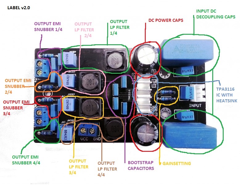
When I checked the board I saw one of the output emi snubber 4.7ohm resistor (close to the speaker output) is not soldered properly. One leg of the resistor is not soldered at all.
So I solder properly and feed it with 17v DC to check. Now one of those resistors gets really hot in few seconds. I got handfull of 4.7ohm resistors so I replaced that one. No change! Is this means the board is defective?
Resistor is marked as Output emi snubber 4/4 in this picture;
An externally hosted image should be here but it was not working when we last tested it.
Resistors 4/4 gets warmer then resistor 2/4, 3/4 gets warmer then 1/4 on YJblue. 4/4 gets warmest of all. Inductors get warmer then other inductors on other boards. Resistorvalue isn't like mine was, or like TI datasheet btw.
3.3 is datasheetvalue. Do you have source and speakers connected?
Resistors 4/4 gets warmer then resistor 2/4, 3/4 gets warmer then 1/4 on YJblue. 4/4 gets warmest of all. Inductors get warmer then other inductors on other boards. Resistorvalue isn't like mine was, or like TI datasheet btw.
3.3 is datasheetvalue. Do you have source and speakers connected?
Thanks for the reply. No source connection or speaker load while I tested the board.
4/4 gets really warm, smells like something is cooking. Is this normal?
Or source and speaker connection is a must before power up?
Thanks for the reply. No source connection or speaker load while I tested the board.
4/4 gets really warm, smells like something is cooking. Is this normal?
Or source and speaker connection is a must before power up?
Yes, resistors now handle all idle output, load is infinite high. Speakers should be connected to prevent enormous peaking, lspeakerload is part of outputfilter. Forgot to say resistors YJblue get warmer then resistors other 3116 ampboards too
Idle the chip does produce output, just out of phase I believe, so this will heat up things normally, just a little more on YJblue
edit: this tread starts with 50V filmcaps in output burning. So also better check the 680nF blocks in outputfilter
Last edited:
l Checked dc offset before speaker connection, right channel has 1.4v dc! Left channel is ok. Further investigation revealed that one 0,68uf cap is not seated to board properly.This cap is part of the 4/4 dc snubber. One leg was chopped of near the capacitor body, not soldered to the board at all.
Can't speak to the YJ three tube 12AU7 preamp, but this is what I and a few others are using:
Yuan Jing Audio - 6N3 + 6Z4 Rectifier Vacuum Tube Pre-Amplifier + Transformer [A] - $45.70
you are right, I am talking about this one,
do you think it is a good upgradable preamp?
Hi dear community
what amp to chose from chinesee varinant on tpa3116
what pcb is better and easear to get even more better by upgrading components?
can start amp 2x50 easy made 1x100?
what amp to chose from chinesee varinant on tpa3116
what pcb is better and easear to get even more better by upgrading components?
can start amp 2x50 easy made 1x100?
The 680uF/25V Panasonic FM caps that are 10mm dia. x 20mm should fit in there if your height measurement is correct. You will need to double-check, but these particular caps have the best combination of ripple current rating and lowest ESR.
Those green film caps on the inputs look like ERO MKT1822 film caps. If they are, I would leave those in there as they are really good caps. However, they can have a lengthy burn-in. With time, they will open up nicely.
The Vishays that are in mine are MKT 1820-77, not much info on the internet about them. I wonder if they are "imitation"
I have some Panasonic FMs I can put inside, but I'm also thinking about Nichicon KZ series, which is a high grade (in Nichicon's lineup) cap, 470uf/25V as well. Not much specs on Ripple and ESR, I think they are a good replacement??
Last edited:
When using a transformer for input DC-decoupling, what's the best way to add volume control?
What I have in mind is:
Input RCA (unbalanced) -> 50k log pot -> Transformer (balanced output) -> tpa3116.
Is that the right "sequence" of components?
What I have in mind is:
Input RCA (unbalanced) -> 50k log pot -> Transformer (balanced output) -> tpa3116.
Is that the right "sequence" of components?
ok!
I'm thinking that what you could do is this schematic.
The Inrush current limiter in this case is the CL-80. I think it's a better fit because it'll use less power to remain at operating ability, and starts at a higher resistance on the days where it might be warm in your home.
You've got a LOT of capacitance on an SMPS, so that explains why you're probably setting off the current limiter within it.
The film caps can be whatever you want. Do you have a few laying around? Left over from a crossover? Basically if you are getting into the hundreds of microfarad it's fine, as the reactance is rather high at DC. They're just for high frequencies that the 4700uf capacitor bank will no longer be effective with. You could have 10x 1uf caps, 2x 4.7uf, 6x 2.2uf. If you're going to order some for it, the naked EPCOSs are nice.
Here's a resistor that'll work for the bleeder. 50ohm, and 20-50w is acceptable.
While this is more complicated, I believe it'll retain a better sound than a straight in-line current limiter that's pre-load and pre-cap-bank.
I'm thinking that what you could do is this schematic.
The Inrush current limiter in this case is the CL-80. I think it's a better fit because it'll use less power to remain at operating ability, and starts at a higher resistance on the days where it might be warm in your home.
You've got a LOT of capacitance on an SMPS, so that explains why you're probably setting off the current limiter within it.
An externally hosted image should be here but it was not working when we last tested it.
The film caps can be whatever you want. Do you have a few laying around? Left over from a crossover? Basically if you are getting into the hundreds of microfarad it's fine, as the reactance is rather high at DC. They're just for high frequencies that the 4700uf capacitor bank will no longer be effective with. You could have 10x 1uf caps, 2x 4.7uf, 6x 2.2uf. If you're going to order some for it, the naked EPCOSs are nice.
Here's a resistor that'll work for the bleeder. 50ohm, and 20-50w is acceptable.
While this is more complicated, I believe it'll retain a better sound than a straight in-line current limiter that's pre-load and pre-cap-bank.
Last edited:
The Vishays that are in mine are MKT 1820-77, not much info on the internet about them. I wonder if they are "imitation"
I have some Panasonic FMs I can put inside, but I'm also thinking about Nichicon KZ series, which is a high grade (in Nichicon's lineup) cap, 470uf/25V as well. Not much specs on Ripple and ESR, I think they are a good replacement??
Cansize KZ might be too big?
Cansize KZ might be too big?
Yes that is a concern,
I know BK856er earlier in the thread fit the Panasonic FM 820uf 25V inside, which are
25mm tall, 10mm wide with lead spacing of 5.0 mm
The nichicon KZ is 25mm tall, 16mm wide and lead spacing of 7.5mm
It may be a bit of a challenge to fit them on the SMSL board.
He mentioned the 25mm is tall enough (with about 5mm left from the top of the enclosure) but if I have to bend the leads, it may add height
I am going to ask Edcor if they would ship via "Priority Mail International®
Small Flat Rate Box" which is $24.75 to New Zealand and much more affordable. Just checked, its the same to France so I will let you know how I get on.
Unfortunately they won't use Flat Rate postage.
Yes that is a concern,
I know BK856er earlier in the thread fit the Panasonic FM 820uf 25V inside, which are
25mm tall, 10mm wide with lead spacing of 5.0 mm
The nichicon KZ is 25mm tall, 16mm wide and lead spacing of 7.5mm
It may be a bit of a challenge to fit them on the SMSL board.
He mentioned the 25mm is tall enough (with about 5mm left from the top of the enclosure) but if I have to bend the leads, it may add height
That silkscreen is 10mm diameter. I'd stick with 10mm body and 5mm lead spacing. Tip = cheaper to buy 10 than 8!
BK
An externally hosted image should be here but it was not working when we last tested it.
Unfortunately they won't use Flat Rate postage.
That's bad!
So many thanks for asking.
Unfortunately they won't use Flat Rate postage.
If it makes you feel any better, even domestic shipping isn't exactly cheap. I went ahead and ordered the TTPC15K/15K, only shipping option was $16 (over 50% of product price). Still cheaper than Lundahls, Jensens, or CineMags. 🙂
Anyone have any comment on volume control with the input trannies?
Also, my source (DAC) has balanced (XLR) outputs, so I'm thinking of going with a fully-balanced setup. I found this post, "Wiring Balanced Volume Pots?", which suggests an easy way to use a standard stereo pot on balanced inputs. See "Configuration B" in this link. That picture suggests putting the pot between the transformer and the amp.
But using something like Emotiva's Control Freak would suggest the pot is between the source and the xformer. (Anyone know what the Control Freak is doing "behind the scenes"? A scheme like suggested above, or maybe a four-gang pot?)
Maybe volume control placement doesn't matter?
If it makes you feel any better, even domestic shipping isn't exactly cheap. I went ahead and ordered the TTPC15K/15K, only shipping option was $16 (over 50% of product price). Still cheaper than Lundahls, Jensens, or CineMags. 🙂
Justa bit!
Yep, been looking at E-Bay for used Lundahls, shipping is a killer there too.
I may still get some Edcors but will wait and see how you like them before ordering. If I get 2 or more sets price starts to drop.
Disregard my first schematic. Sorry, here's the correct one. My apologies for not editing it soon enough (I hate that about this forum, no editing after a short period)

If it makes you feel any better, even domestic shipping isn't exactly cheap. I went ahead and ordered the TTPC15K/15K, only shipping option was $16 (over 50% of product price). Still cheaper than Lundahls, Jensens, or CineMags. 🙂
Anyone have any comment on volume control with the input trannies?
Also, my source (DAC) has balanced (XLR) outputs, so I'm thinking of going with a fully-balanced setup. I found this post, "Wiring Balanced Volume Pots?", which suggests an easy way to use a standard stereo pot on balanced inputs. See "Configuration B" in this link. That picture suggests putting the pot between the transformer and the amp.
But using something like Emotiva's Control Freak would suggest the pot is between the source and the xformer. (Anyone know what the Control Freak is doing "behind the scenes"? A scheme like suggested above, or maybe a four-gang pot?)
Maybe volume control placement doesn't matter?
The link you provided with Configuration B on Figure 17 is your best option. Keep in mind that you will need either two dual-gang attenuators or a four-gang attenuator. Since you are working with differential inputs or a balanced circuit, the match between your gang for the "+" side and the gang for the "-" side need to be matched very closely. A budget-priced 20k or 50k Panasonic EVJ volume pot may not be the best solution, but it could still work if the channel 1 and channel 2 resistive elements are close enough. A four-gang stepped attenuator using closely matched resistors is probably the best solution.
With my set-up of the YJ blue amp and the CineMag transformers, I have a pair of 30k Vishay-Dale RN60 1% metal film resistors wired across the "+" and "-" inputs (i.e., transformer secondaries) to match the amp's 30k input impedance (26dB gain). KJA 2013 suggested I use tighter tolerance resistors, which I may try, although I really am enjoying the amp in its current state.
- Home
- Amplifiers
- Class D
- TPA3116D2 Amp