My newest 3116 board has a louder turn on pop than the others which made me recall the forum comments about pops. There is really a lot to sort through.
If one of you brilliant guys could please add a section to the WIKI I'm sure some of us noobs would be grateful. 😀
If one of you brilliant guys could please add a section to the WIKI I'm sure some of us noobs would be grateful. 😀
I am not suggesting different values just wondering if variation in parts from YJ a today may be cause. Mine happens to have 560nF for main LC filter and 5.6R for snubber vs 3.3R as recommended.
Hi Xrk971,
Thank you very much for your answer,
I am going to check for that.
anyway this board sounds good.
If the output filter on these amps primarily effects the very top end (10K-20KHz) then shouldn't the filter values be set for the loudspeaker impedance at these frequencies?
I ask because a typical 4ohm impedance full range loudspeaker will often be >7ohms above 10KHz, which would suggest that an output filter designed for an 8ohm load should be more appropriate.
I ask because a typical 4ohm impedance full range loudspeaker will often be >7ohms above 10KHz, which would suggest that an output filter designed for an 8ohm load should be more appropriate.
Sure, but it has by far the greatest effect on the very top end, so aligning the filter for that impedance load must have the greatest impact.
Class-D Amplifiers
Class-D Amplifiers
Now enjoy the coffee with my new TPA Amp.

Hiamplifier, that is a neat way of connecting your inputs and volume pot. Would you help me find these cables and boards? I would like to have a few handy for future projects.
Xrk971, when I really push the amplifier to the max and hit hard bass it just plays the tunes as normal.. Earlier I belive I could hear some artifacts. I am waiting for 22uF ceramic smd capacitors and I will use a pair of those on each side instead of the Jamicons. I use a switching powersupply so I don't need large values in this particular setup.
I belive in keeping the components small and close to the chip/grounding plane. I do belive most of the improvements people are getting is just reduction in noise. I've done large expensive components mods earlier with less success that the short and small method. I have 4 working boards now which I have tried all mods except the 330pF RC mod which is going in soon. I'm going to do some more listening and comparisons between the boards and then report back on improvements using film smds. But on paper the film smd have lower ESR than ceramics.
I belive in keeping the components small and close to the chip/grounding plane. I do belive most of the improvements people are getting is just reduction in noise. I've done large expensive components mods earlier with less success that the short and small method. I have 4 working boards now which I have tried all mods except the 330pF RC mod which is going in soon. I'm going to do some more listening and comparisons between the boards and then report back on improvements using film smds. But on paper the film smd have lower ESR than ceramics.
There is a calculation somewhere in TI datasheets what tpa3116 chip needs close to pins during cycle, 220uF delivers that when close to pins...
If you want to improve noise look at 0.1uF decoupling position and move them closer, (they can be closer if you don't mind soldering directly onto chippins)
If you want to improve noise look at 0.1uF decoupling position and move them closer, (they can be closer if you don't mind soldering directly onto chippins)
Attachments
+1 on the 220uF minimum. I think if you look at how much energy 22uF is and draw that out on a single high impulse kick drum beat, you will deplete the cap. That is why we are using 330uF OSCON caps and many people use bigger but then it doesn't add anything.
Here is my newest 3116 YJ blue/black board. The power, input caps and gain resistor has been changed. Power is right at the max 26V, which is a little bit of a concern but it doesn't seem to get hot. So I will hope for the best 😉
I'd love to hear any comments.
cheers- prezden
I'd love to hear any comments.
cheers- prezden
Attachments
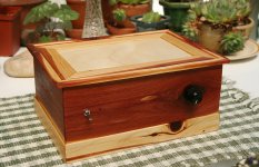
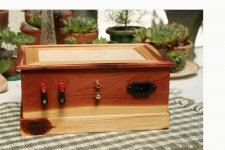
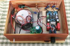
Very nice work Prezden! Is that a cedar box? Where do you get all your wooden project boxes? Are they custom made by yourself or you have a convenient source of ready made ones? How many amps does that toroidal transformer provide at 26 volts? Is there a regulator or that is just full bridge rectified and filtered take what you get?
How does it sound?
How does it sound?
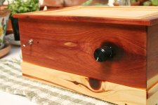
Hi x- Thanks. The cabinet is made from aromatic cedar that is milled in 3/8" thickness for lining cedar chests. Each one is custom designed and built for the amp. The toroid in this one is a 9 0 9 centre tapped. After the regulator I end up with 26V. It's what I had lying around from an older project that I blew up.
It sounds great with my Mini Onkins with an old Marantz cd player for a source. I've only listened to a couple discs- Leonard Coen's ten new songs and Sarah Brightman's classics. I would venture to say it the best amp I have made so far.
It sounds great with my Mini Onkins with an old Marantz cd player for a source. I've only listened to a couple discs- Leonard Coen's ten new songs and Sarah Brightman's classics. I would venture to say it the best amp I have made so far.
I didn't have a spare 19V laptop brick kicking around, but I did have a "clone" of the Astron RS-4 regulated linear power supply @ 13.8V/3amp. Some wire cutters and a couple banana plugs and I was all set. I think it did smooth out the SMSL TPA3118 a little bit compared to the 12V SMPS the unit shipped with.
BK
I've now tried the following power supplies:
- SMSL supplied 12V/3A small brick
- Linear regulated 13.8V/3A
- Lenovo 20V/8.5A huge brick
- AMB sigma-11 discrete linear regulated 12V
So far I have a strong preference for the linear regulated supplies, and the AMB is my winner. It was previously powering my DAC @5V, but I reconfigured it for 12V with a single zener swap and a 15V toroid. I will probably build one up for this TPA3118 amp and probably up the voltage.
AMB says the s11 is good for 1A continuous with the onboard heatsinks, and will supply much, much higher peak currents when called on. Continuous current over ~1A requires off-board heatsinks. My onboard heatsinks are measuring only 35C - barely warm. Load is 6ohm, 87dB full-rangers for desktop use.
I measured very low current draw with my DMM. Does the TPA3118 amp really draw over 1A? I'll need to spec out a toroid for the sigma-11, but don't want to under/over do it. Any suggestions?
BK
3110, so take highest and overdo it a little 😛
http://www.ti.com/lit/ds/symlink/tpa3110d2.pdf
figure 26 and figure 34
http://www.ti.com/lit/ds/symlink/tpa3110d2.pdf
figure 26 and figure 34
An upgrade: I admit I don't understand the math behind figuring out the exact combination for the LC output filter - but I thought math is one thing, my ears something else. And what I somehow cannot stand is HF 'glare' - so the aim was keeping HF information but without sounding unpleasant. Thus I played around with the capacitor values in my board (remember: the coils are 22uH).
It began with the installed 0,56uF - subjective evaluation: not too bad, but let's see...
Next step: 0,68uF - struck me as already mor to my taste.
Why not add another 0,22? - oh yes, it's getting 'better'
Final step: 1uF - and suddenly -'bingo'! To my ears (and with my speakers!) that is the combo that removes the 'glare' and seems thereby to reveal instrumental 'colours' and low level details quite a bit more.
Conclusion: it's a very worthwhile exercise to play around with the LC output - making a difference in the magnitude of transformer input and/or coil replacement.
Good idea about just playing with output LC filter and listening. If your ears like it that is the test.
I too have 22uH and 1uF film smd capacitors and I think they sound better than 0,68uF.
Irribeo, I have done that mod too on some of my boards but I don't think its enough to remove the noise the large electrolytics pick up.
Well its going to be 44uF on each side and upwards from there. The leads to psu will only be 7-8cm so hopefully its going to be enough.
Irribeo, I have done that mod too on some of my boards but I don't think its enough to remove the noise the large electrolytics pick up.
Well its going to be 44uF on each side and upwards from there. The leads to psu will only be 7-8cm so hopefully its going to be enough.
Last edited:
decoupling is done to filter noise and to make ampboard less dependant on PSU, both only work when distance is mm, not cm like both YJ boards.
giving the tpachip less clean and generally less instant power might seem to work, only if it masks another problem, imo
(I don't know what the Jamicons do, but nothing positive I am told, productioncode 944C0 that is)
giving the tpachip less clean and generally less instant power might seem to work, only if it masks another problem, imo
(I don't know what the Jamicons do, but nothing positive I am told, productioncode 944C0 that is)
3110, so take highest and overdo it a little 😛
http://www.ti.com/lit/ds/symlink/tpa3110d2.pdf
figure 26 and figure 34
That helps, thanks. Interesting that the different chips have different levels of detail/info in the spec sheets.
I noticed the TI eval boards specify 8A supply. I suppose that's to give a lot of headroom for test tones, various loads, peaks, etc. My power needs (nearfield, music, easy load) seem to be very modest based on my ammeter measurements/PS heatsink temps/listening tests.
I have an 80VA toroid on there now. Smaller 25 or 50VA should do the trick.
BK
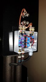
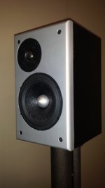
So I've been listening to two ChengZhi boards (first attachment) I've used to bi-amp some studio monitors(second attachment) I built last winter. I'm happy with the results and feel the tpa3116 is a great chip. Now that I have listened to the setup for some time now (4months) I would like to modify the tpa board to see what I can get. The bass response seems to roll off on the bottom and the highs seem to rise on the top end. So far I've been using my minidsp to correct this and would like to try and fix some of the response issues on the board.
To try and correct the bass response, I would like to change the input caps from 1uf to 3.3uf and/or change the gain to 20db (this may also help with the small amount of hiss I get from the tweeter).
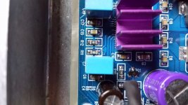
I'm new to working with circuit boards and have a few questions...(third attachment)
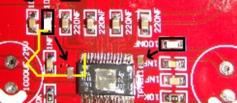
Based on the tpa application sheet, It looks like chengzhi mixed up resistors numbers R12 and R11 (third attachment). R12 is 100k and R11 is 20k (26db). To change the gain to 20db, would I just remove the resistor from R12 leaving it open and replace the 20k resistor with 5.6k? Other than the correct case size for the smd resistor, which I haven't determined yet, what should i be looking for? % w...
C19, C17, C7, and C6 seem to be the input caps, two being through hole and two being smd. The through hole cap is 1uf 63v and measure 7mm x 4mm not sure what the smd is. The only through hole 3.3uf cap I have found so far that will fit is a x7r 50v ceramic cap (digi-key# 445-8459-ND) Is this cap sufficient? I would like to use a film cap but they are all too large. Also, is it best to replace smd caps with similar specs?
Based on discussions in this thread, I'm guessing that the top end response issues have to due with my speaker impedance. The board I have looks like is was optimized for 4ohm load and my speakers are both 8ohm. I'm going to change the 10uh inductors out for 22uh and see what happens.
Thanks for your help in advance with component selection.
Ian
To try and correct the bass response, I would like to change the input caps from 1uf to 3.3uf and/or change the gain to 20db (this may also help with the small amount of hiss I get from the tweeter).
I'm new to working with circuit boards and have a few questions...(third attachment)
Based on the tpa application sheet, It looks like chengzhi mixed up resistors numbers R12 and R11 (third attachment). R12 is 100k and R11 is 20k (26db). To change the gain to 20db, would I just remove the resistor from R12 leaving it open and replace the 20k resistor with 5.6k? Other than the correct case size for the smd resistor, which I haven't determined yet, what should i be looking for? % w...
C19, C17, C7, and C6 seem to be the input caps, two being through hole and two being smd. The through hole cap is 1uf 63v and measure 7mm x 4mm not sure what the smd is. The only through hole 3.3uf cap I have found so far that will fit is a x7r 50v ceramic cap (digi-key# 445-8459-ND) Is this cap sufficient? I would like to use a film cap but they are all too large. Also, is it best to replace smd caps with similar specs?
Based on discussions in this thread, I'm guessing that the top end response issues have to due with my speaker impedance. The board I have looks like is was optimized for 4ohm load and my speakers are both 8ohm. I'm going to change the 10uh inductors out for 22uh and see what happens.
Thanks for your help in advance with component selection.
Ian
Attachments
- Home
- Amplifiers
- Class D
- TPA3116D2 Amp