Read "audiocircle". I heard board with jamicons and after, you need to replace them anyway, good chance problem is also there, they did measure like condensators!!! You said "distorted'' and "quiet" and that is remarkably like the board I heard!!!
This weekend, I completed my second tpa3116 amp using a modified YJ blue/black board. I made a number of changes:
Pics:
If you look closely, you'll see some poorly trimmed leads, particularly from the output filter caps. Those were corrected after I took the pictures.
It's far from the last word in neatness, but definitely my cleanest work to date. Thanks to Rhing and others for providing numerous tips on mounting those big inductors.
I didn't have a lot of time to listen to it, but it seems pretty decent. One thing that surprised me, changing the gain one "notch" up (from stock 26 to 30) made a pretty big difference in loudness. I think even with my living room rig, I could get by with a smaller power supply when using the louder gain setting (currently using 24V SMPS brick from YJ).
However, there is a slight hissing sound when music is playing. Many pages ago, I remarked that my first YJ blue/black board hissed when inputs were not connected (or source device was powered off).
This is a completely different phenomenon. As far as I can tell, the amp is dead silent, until music starts playing, at which point there is a faint background hiss. It's really only noticeable during quiet parts of the song (typically intro fade-in/outro fade-out), otherwise the music drowns it out.
It's (perhaps not surprisingly) more noticeable on my desktop system, where my speakers are about two or three feet from my ears. This amp was designed to go in my living room rig, where the listing distance is at least 10 feet; at that distance, the hiss cannot be heard at all.
It comes out equally from both channels.
Anyone experience anything like this? Unfortunately, I was too impatient to test the board before modifying it. Not sure if it shipped with the hiss or the hiss is due to my mods.
I know those output filter capacitor leads are a little suspicious, given how long they are, but I have another blue/black board that I used the same caps the same way, and it doesn't suffer this problem.
My guess is that it has to do with changing the gain, making it more sensitive to input noise... but I dunno.
- power supply caps swapped for Panasonic ZA
- gain changed to 30
- bootstrap caps swapped for the TDK X7R
- output filter inductors swapped for the big Coilcraft ones
- output filter caps swapped for Panasonic PP (had to be moved to bottom of board)
- power input terminal block moved to bottom of board
Pics:
An externally hosted image should be here but it was not working when we last tested it.
An externally hosted image should be here but it was not working when we last tested it.
An externally hosted image should be here but it was not working when we last tested it.
If you look closely, you'll see some poorly trimmed leads, particularly from the output filter caps. Those were corrected after I took the pictures.
It's far from the last word in neatness, but definitely my cleanest work to date. Thanks to Rhing and others for providing numerous tips on mounting those big inductors.
I didn't have a lot of time to listen to it, but it seems pretty decent. One thing that surprised me, changing the gain one "notch" up (from stock 26 to 30) made a pretty big difference in loudness. I think even with my living room rig, I could get by with a smaller power supply when using the louder gain setting (currently using 24V SMPS brick from YJ).
However, there is a slight hissing sound when music is playing. Many pages ago, I remarked that my first YJ blue/black board hissed when inputs were not connected (or source device was powered off).
This is a completely different phenomenon. As far as I can tell, the amp is dead silent, until music starts playing, at which point there is a faint background hiss. It's really only noticeable during quiet parts of the song (typically intro fade-in/outro fade-out), otherwise the music drowns it out.
It's (perhaps not surprisingly) more noticeable on my desktop system, where my speakers are about two or three feet from my ears. This amp was designed to go in my living room rig, where the listing distance is at least 10 feet; at that distance, the hiss cannot be heard at all.
It comes out equally from both channels.
Anyone experience anything like this? Unfortunately, I was too impatient to test the board before modifying it. Not sure if it shipped with the hiss or the hiss is due to my mods.
I know those output filter capacitor leads are a little suspicious, given how long they are, but I have another blue/black board that I used the same caps the same way, and it doesn't suffer this problem.
My guess is that it has to do with changing the gain, making it more sensitive to input noise... but I dunno.
Hi,
I have a YJ 2.0 red board (stock, with only changed pot) - and I have the usual turn-on "speaker pop" problem.
I've tried solution from p 172 of this thread (with 100 uF 25V electrolytic cap), but it doesn't help...
Is there a definitive solution to turn-on pop for red 2.0 boards?
johhnygrace had a similar problem, and many others, but the only solution was a cap between ground and 100K resistor tied to SDZ pin - e.g. as in photos in post #2492 by johhnygrace....
Anything else I could try before I start fiddling with relays?
I'm planning to put the TPA3116 into the same enclosure with my Raspberry Pi + Wolfson audio card (24/192 capability, excellent sound) to make an all-in-one audio server + amp (most likely with 20x4 LCD and IR remote), and the only problem left is this annoying (and unpleasant) turn-on speaker pop when I turn on the power...
I know that I can avoid it if I turn down the volume using the pot, but that's not a foolproof solution...
Giancarlo's solution works for me:
Forums - Audio Amplifiers Forum - Audio Amplifiers - TI E2E Community
Scroll to the bottom and you will see the schematic. I used a regular diode in place of the diode he suggested and it still works perfectly.
-AC
Power output in PBTL mode
Over in DUGs GB thread I asked the following question:
I am a little unclear as to the resulting power available from PBTL. The datasheet says "MONO mode enabling up to 100W output power" and the circuit diagram shows 100watt into 2 ohm. Do you get 100watt into 4 or 8 ohm or is the output reduced? I assume the LC filter will need adjustment for the impedance being driven, is this designed on same basis as straight BTL amplifier?
DUG answered "----There seems to be a lot of people here that will answer the power question after they build and test. All I can answer is what the data sheet has…Fig 22."
I am confused because the datasheet only talks about PBTL being 100watt into 2ohm. So what is the situation with a regular 4-8ohm load for a dual momo pair of the PBTLs? Anybody able to enlighten me?
PBTL power is 1 to 1.5 watts above BTL, you could say they are equal 🙂
PBTL power is 1 to 1.5 watts above BTL, you could say they are equal 🙂
OK, thanks. So, assuming 4-8 ohm speakers, the advantage of PBTL is in its being "dual mono" not a gain in power. The power gain comes if you are needing to drive a 2ohm load (say dual 4ohm subs wired in parallel).
And the way you derive the values for the LC filter is the same as BTL?
OK, thanks. So, assuming 4-8 ohm speakers, the advantage of PBTL is in its being "dual mono" not a gain in power. The power gain comes if you are needing to drive a 2ohm load (say dual 4ohm subs wired in parallel).
And the way you derive the values for the LC filter is the same as BTL?
Filter is calculated same way. load/2, filtercap*2 L=L in SE filtercalculator........that is when there are just 2 inductors per channel, not sure what happens if you have a complete stereo board and tie outputs together.......
Dual mono appears a little more stable in soundstage here. Also noise should be more equal if there was a difference between left and right that is (I felt there was/is).
edit:2 outputs together on stereoboard probably means 4*filtercap value for single ended formula, I think the caps remain in signalpath then.
Last edited:
Giancarlo's solution works for me:
Forums - Audio Amplifiers Forum - Audio Amplifiers - TI E2E Community
Scroll to the bottom and you will see the schematic. I used a regular diode in place of the diode he suggested and it still works perfectly.
-AC
Thanks, will try that one!
So, for D1, any Schottky diode should be OK, I guess?
As for C1, increasing the cap value (e.g. 10uF/50V) should generally make the delay longer, if I understand correctly?
Thanks!
just curious, when you mute(/sdz) then when unmute 20dB gain is selected I believe, like some reported, not sure why, but will this mute/unmute circuit disable gainsettings too?
I thought gain reset only occurs with hard power off/on cycle? I have successfully used mute (not above circuit) before with 26dB gain and it seems fine.
So I thought that I bypassed the preamp when I put the input audio signal direct in front of the input cap (1uF), but it turns out that the treble adjustment still works, so that means that the preamp still works? Could anyone show me how to correctly bypass the preamp?
Thank you.
If anyone is interested, it was the preamp that was faulty, just figured it out today that I can bypass the preamp if I detach the input capacitor 🙂 now it works fine when I connect the audio signal direct to the chip without the preamp.
just curious, when you mute(/sdz) then when unmute 20dB gain is selected I believe, like some reported, not sure why, but will this mute/unmute circuit disable gainsettings too?
From datasheet: "The gain setting is latched during power-up and cannot be changed while device is powered"
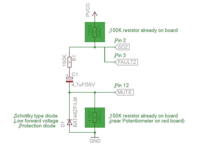
The above circuit does not interfere with the proper operation of the amplifier.
Anyway SDZ is always deactivated, because is at high logic level and only MUTE pin is active for for a short time after power-on.
The delay depends by C1 value, power supply voltage and only minimally by R1.
With 21V of power supply and values in the schematic, the delay is about 1.8 seconds.
Doubling C1 will double the delay.
The lower the value of power supply, the lower the delay time.
Without R1 (0 ohm ) the delay will be about 1.5 seconds.
So, why have I added R1?
'cause in case of fault condition, like for example overtemperature,"FAULTZ" pin, that is connected to "SDZ" pin, goes to low logic level and R1 will limit C1 discharge current.
In such a case, without R1, there would be a very high spike of current on "FAULTZ" & "SDZ" pins.
About D1:
Probably I'm overly cautious strictly indicating the use of a schottky diode for D1, but this is only for a safety reason, 'cause in the datasheet has been indicated an absolute limit of only -0.3V for "MUTE" pin.
With a Schottky diode, the voltage on mute pin will be -0.25V, and so within that limit.
With a regular (silicon) diode, the voltage on mute pin will be about -0.5...-0.6V, that is above the limit.
I dunno if a brief voltage of -0.6V could be damage the chip on long term, very probably not, but it cannot be guaranteed 100%
I was planning to have dual monos to have more power but it looks like this is not the case. If cost is no object, would having monos give any advantage at all?
Last edited:
Giancarlo, thanks for the schematic, photos and the explanation. Much clearer now...
Will report in a day or two, once I get the parts I need (schottky) and once it's soldered and tested.
Thanks!
Will report in a day or two, once I get the parts I need (schottky) and once it's soldered and tested.
Thanks!
I thought gain reset only occurs with hard power off/on cycle? I have successfully used mute (not above circuit) before with 26dB gain and it seems fine.
shorting sd and mute in that extra connector on ydbz(green but blue in your case) mutes amp doesn't it? if you are using 2 boards and mute 1 of them and wait few seconds and unmute, does it play as loud as the other that is still playing??????? like I said, some reported it will go to 20dB gain. ( I can not check, all my amps are in 20dB gain already)
YJ 2.0 speaker turn-on pop - SOLVED!
I managed to find a schottky diode that I needed for Giancarlo's solution - and in about 10 minutes managed to solder everything together, following his instructions on the TI forums site (see earlier link).
I used a BAT46 diode, 10uF/35V capacitor, and 150K resistor, according to Giancarlo's scheme...
I'm happy to say that my turn-on pop problem is solved 🙂
Thanks everyone, and in particular, big thanks to Giancarlo!
Well done, den_hr!
I'm very glad I was able to help you and other guys to solve the annoying turn-on pop!
I'm very glad I was able to help you and other guys to solve the annoying turn-on pop!
I was planning to have dual monos to have more power but it looks like this is not the case. If cost is no object, would having monos give any advantage at all?
I'm also very interested to hear, because was planing exactly the same.
- Home
- Amplifiers
- Class D
- TPA3116D2 Amp