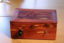
I just finished boxing up one of the 3116's. No mods on this one. Playing with a pair of 24" FC Cornus using TB W4 Bamboo drivers they sound great 😀
In hind sight I wish I had made the box a bit bigger in order to managed the wires better 😱 Next one.
In hind sight I wish I had made the box a bit bigger in order to managed the wires better 😱 Next one.
Attachments

I started to modify on of the blue/black boards. First I replaced the power caps with 2200 Panasonic FC's. The light on my dim light tester kept flashing on and off. I then switched to 1500 Panasonics and it is fine. 😕
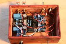
Hi I hope you allow me to give some comments. Your board should be turned as the speaker wires now cross with the unshielded input cabling. This is not good as the board emits EMI that gets picked up by the inputs. YJ includes a shielded cable in the package, it is better to use that one in all cases.
The way it is now all input and output wires cross except for the power wiring (which is the least critical). It is standard practice to keep inputs and outputs at separate sides. The potentiometer is opposite the inputs the way it is now...You would need to switch potentiometer and power switch when you turn the board.
Power input jack is normally not near the inputs and DC should not be switched, it is better to switch at the AC side.
Last edited:
Thanks jean-paul. I don't mind your feed back at all- it is most welcome.
If I am understanding you correctly I've got the inputs where the outputs should be and visa versa.
How do you switch at the AC side when using an external AC/DC adaptor?
If I am understanding you correctly I've got the inputs where the outputs should be and visa versa.
How do you switch at the AC side when using an external AC/DC adaptor?
...
How do you switch at the AC side when using an external AC/DC adaptor?
Switched power bar.
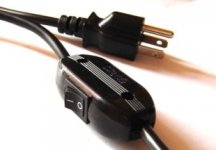
This for instance 😉
This looks like the switch on one of my floor standing lamp. Good idea.
Regards,
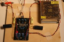
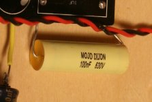
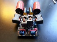
I've been messing around with another yj blue/black board. Mods are with 1500 Muse power caps and MoJo Dijon 100nf for input caps. To my untrained ear there is a substantial improvement over the stock board.
At first I used 1500 Panasonic FC caps and then tried the Muse. The Muse sounded better than the Panasonic for me.
Any suggestions on components and especially layout would be much appreciated. 🙂
At first I used 1500 Panasonic FC caps and then tried the Muse. The Muse sounded better than the Panasonic for me.
Any suggestions on components and especially layout would be much appreciated. 🙂
Attachments
I've been messing around with another yj blue/black board. Mods are with 1500 Muse power caps and MoJo Dijon 100nf for input caps. To my untrained ear there is a substantial improvement over the stock board.
At first I used 1500 Panasonic FC caps and then tried the Muse. The Muse sounded better than the Panasonic for me.
Any suggestions on components and especially layout would be much appreciated. 🙂
100nf?
wushuliu- I had them lying around 😕
Don't input caps that small affect the response?
Neat.
Aftermarket source?
Just googled those. We have other plugs here. If you will use such a cord please choose one with a sturdy switch. I know these are used for lamps 🙂 but this is a better solution than switching DC. Also no sparks and damaged contacts of the DC jack and plug when switching AC. Once it was taught in school that switching DC was to be avoided but apparently chinese engineers missed that class..
Last edited:
100nf?
wushuliu
It is in the picture!! He used a 100 nF (0.1 uF) caps at the input. I think this is the reason why the sound "improved". Well as long as he likes the sound, it does not really matter, right?
@prezden,
wushuliu raised the question because in the TI data sheet (bottom of p 15), the listed recommended values of capacitance are in the range of single digit uf. These values are proposed based on the input impedance of the amp and will provide specific ranges of frequency response. There is nothing wrong when you place a small valued input cap, just that the frequency response is changed (I think the bass frequency roll-off is raised). Hey, you like the sound, that's the only thing that matters.
Regards,
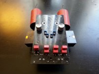
WOW I must say, thought it wasn't possible (I missed that 3rd connection was only for stability so I saw them only lying flat or wired)
Those flat wires are like plates, huge😀
Those flat wires are like plates, huge😀
Wow!!! Incredible, you managed to "squeeze" those humongous inductors on!!
How is the sound?
Regards,
Where are the DC decoupling caps?
Attachments
The hybrids too, cool. Can't really understand datasheet for ripple and translation into sound when used. Lack of tech knowledge I am affraid. For high frequencies these compare to bigger Ecaps, but for the lower audio frequencies they have same values as equal rated Ecaps and all that probably doesn't mean anything for bulk function?? I am too stupid here🙂
- Home
- Amplifiers
- Class D
- TPA3116D2 Amp