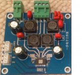
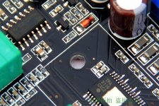
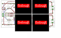
Those CC inductors look really nice - I have never seen such a high tech looking coil. The wire is flat even! Will they really improve the sound? I am curious and would do this if folks think it helps.
I suspect they will improve the sound. However they're not the lowest hanging fruit, the power supply is.
I suspect they will improve the sound. However they're not the lowest hanging fruit, the power supply is.
True ... but they're the second lowest would you not agree? And by power supply, I take it you mean close-as-possible SM HF caps like the "weiner"?

http://www.diyaudio.com/forums/class-d/237086-tpa3116d2-amp-232.html#post3864876
and the "Mr. Tao"

http://www.diyaudio.com/forums/class-d/237086-tpa3116d2-amp-242.html#post3868604
Given that HF PS SM caps are usually dictated by the PCB perhaps the lowest hanging easily DIY fruit can go to the output inductors?
Last edited:
Only the wires needed to connect them might spoil dcr and some 🙂 you guys are joking aint you😕
Excellent point, please continue gentlemen so that we can settle on a good output inductor upgrade ...
I just read a remark about this chip decoupling and also read something RNN Marsh said about paralel/bypass caps and canceling/reducing operating frequencies. Could abraxilito being an experienced and knowledgeable designer comment on using both a 1nF AND a 100nF decoupling cap by TI datasheet here? Is this seen in other "good" 400Khz designs or is it like the remark I read suggested just "fashionable"? Is it harmless? What value decoupling cap would abraxilito pick for lets say 20V DC input into this chip operating at standard ~400khz ?
If protectioncircuit trips ~7.5A and distortion for our little chip has reached>30% by then I would think a 7A rated inductor would already be better then needed really. But that probably isn't only difference between inductors🙂
If protectioncircuit trips ~7.5A and distortion for our little chip has reached>30% by then I would think a 7A rated inductor would already be better then needed really. But that probably isn't only difference between inductors🙂
What's with calling the Ybdz 2.0 amp the 'Wiener'? As in winner? It does have one of the best layouts IMO. I will upgrade the stock PS caps to 1500 uF Panasonic FC's soon to see if it helps. I think one of the biggest overlooked upgrades is to change the 1uF input caps to 5.6uF - there is no harm and only upside is improved bass extension down to 20 Hz correct?
For decoupling a chip such as this, using 1nF is just a fashion statement, it really can serve no useful purpose at all. What's needed for the chip to give of its best is milliohm level impedance across the band from 40Hz up to the switching freq. Its harmless in one sense but it still takes up space near the chip which could be used by a much larger value. I'd say a substantial array of 10uF/25V (or higher voltage) 1206 X5R or X7R chip caps needs to be used.
Last edited:
What's with calling the Ybdz 2.0 amp the 'Wiener'? As in winner? ...
Yep,

Two birds, one stone as it were ... (see last comment ...)
...I think one of the biggest overlooked upgrades is to change the 1uF input caps to 5.6uF - there is no harm and only upside is improved bass extension down to 20 Hz correct?
I got a weird turn on osc with oversized input caps, keep the mute on longer.
Last edited:
For decoupling a chip such as this, using 1nF is just a fashion statement, it really can serve no useful purpose at all. What's needed for the chip to give of its best is milliohm level impedance across the band from 40Hz up to the switching freq. Its harmless in one sense but it still takes up space near the chip which could be used by a much larger value. I'd say a substantial array of 10uF/25V (or higher voltage) 1206 X5R or X7R chip caps needs to be used.
Ok, now I'm confused ... I thought the Weiner and the Mr. Tao were generally considered proper PS bypassing with proper components for the TPA3116??? And I was just about to buy them ... And I'm not technical enough to make proper arguments so others who are please jump in ...
Weiner

Mr. Tao

They are considered proper (in the sense of PC) - IOW they are as recommended by TI. But bear in mind that TI recommend NE5534 as I/V for their DACs. So opamps are the proper (PC) solution for DACs' output stages. Nuff said?
Guys (any gals?) on this thread in general though will find they have to dispense with the proper things in search of what sounds best. What sounds awesome is a long way from being proper in the EE sense.
Guys (any gals?) on this thread in general though will find they have to dispense with the proper things in search of what sounds best. What sounds awesome is a long way from being proper in the EE sense.
Psu layout design could be good by the Weiner, problem is smd don't show what they are, so weiner could easily be worst performing pcb on market distortionwise. Components can indeed be replaced, smd is just tiny bit harder, I rather add a decoupling ceramic cap 1mm from chip myself on another pcb knowing it is just that smd I got to solder lol
Exactly!Guys (any gals?) on this thread in general though will find they have to dispense with the proper things in search of what sounds best. What sounds awesome is a long way from being proper in the EE sense.
I was on mobile once again and did not see several entries🙂 looks like 1 or 2 smd parts is a bit low🙂 I can be flexible🙂
Nice data sheet for the coilcraft ser2915l:
yes you will need 60mmx60mm pcb just for 4 inductors, I think best to order biggest pcb's you can find to conclude they won't fit
Yup. I love their looks too but they are big - ~ 28 mm x 20 mm.
Regards,
Yup. I love their looks too but they are big - ~ 28 mm x 20 mm.
Regards,
I think a little ingenuity will allow them to fit the yj blue board...
For those wanting to retrofit inductors neatly onto their existing board, the CC RFS1412 range looks ideal (144mm dia, 12mm high). A bit higher DCR but still probably more than adequate.
So I can't seem to get rid of the speaker pop so I bought this ebay board hoping it would be a good solution......
15A Current relay Speaker protection board Kit for DIY kits | eBay
This link has a word doc that is somewhat more helpful, maybe someone can make sense of it.....
Speaker Protection Assembled Finished Board DIY Kit - Blue - Free Shipping - DealExtreme
I've soldered up two of them now without getting either to work. The led lights up and everything. Pretty sure my solder joints are fine. It's confusing to me that it lists the speaker wire hookup points as "IN" and "GND." Is that Chinese for "+" and "-" ? Would seem to make sense that way. And for power supply it's listed as "AC" and "INPUT"
Another question is why on the PCB do some of the solder holes for the relay have a smaller diameter ring of solder around them... was I supposed to leave some of them unsoldered?
Hoping someone has used this before and it works and can let me know how they hooked it up...starting to get frustrated with this red YJ board...why no speaker protection. I could have just ordered one of those board with speaker protection and been done with it.
Anyone found a TPA3116D2 board with a potentiometer and speaker protection?
johnnygrace,
Speaker protection?
Knowing that the tpa3116 is a btl design?
and this protection ckt does what?
I don't use a 3116 but have a 3100 and it does not require any protection or has any turn-on transient pop, but I am using a mcu to control the sdnx and mute pins so your design is seems not to be dealing with the control of these pins properly, unless your popping is from a prior stage.
Do you get popping with the 3116 inputs grounded?
Rsaves,
are you talking about grounding the power input or audio signal inputs?
how might i go about grounding the audio inputs to the 3116? Im currently using a sure audio bluetooth module as the input, via a 3.5mm stereo jack.
are you talking about grounding the power input or audio signal inputs?
how might i go about grounding the audio inputs to the 3116? Im currently using a sure audio bluetooth module as the input, via a 3.5mm stereo jack.
- Home
- Amplifiers
- Class D
- TPA3116D2 Amp
