😀 First thing one would expect is EVM to be according to advice TI hands with 3116, funny enough it isn't. Personally I think I prefer 100nF cog and 10uF classII for both sides.
I have 2 weiner boards. To me the overall sound is very good but they lack in power compared to the YJ blue/black boards I have in various levels of modification. I changed the caps to OSCON's on both boards. One is powered by a 24v supply from DigiKi, the other with a 19v laptop brick.
Attachments
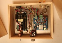
I have 2 weiner boards. To me the overall sound is very good but they lack in power compared to the YJ blue/black boards I have in various levels of modification. I changed the caps to OSCON's on both boards. One is powered by a 24v supply from DigiKi, the other with a 19v laptop brick.
Maybe inductors are 0.5A max befor saturating🙂 Who knows? But they do have 6-10uF on gvdd pin like I mentioned befor, don't know if that influences behavior, filter is completely 8ohm, so most likely better match for most speakers but not for all. Decoupling if I remember correctly 10nF and 1uF classII, so these are then much closer to TI's advice than own EVM 🙂 When changing outputfilter values these YdbZ are very predictable, unlike ac1308/audiobah for instance that can have opposite results from expected, probably because filterfrequency standard ac1308/audiobah is low or maybe something else???
😀 First thing one would expect is EVM to be according to advice TI hands with 3116, funny enough it isn't. Personally I think I prefer 100nF cog and 10uF classII for both sides.
Newbie question: which should be 100NF on Black/Blue board and which one 10uF? Some good examples from Mouser etc co.?
Which one is tour personal favorite TPA3116D2 board?
Thank you!
I can't but help to notice the large distance between chip and psu caps. In all my cards it has really helped to move them "onto" the chip. I also upgraded the chokes to larger ones which removes all compression in the sound. Of course all this is old news, but I really whish someone could make a board with psu trough-hole caps underneath the board, directly into the chip legs. And also use more trough holes to put the bootstraps even closer to the chip. In my experience that makes the card super quiet (abolutely no hiss). I put a stock card in my pc desktop amp and it has hiss like crazy! In contrast to my ultra modded Hifi 2.0 which really has become a delight to listen to🙂
Yes YJblueblack doesn't have a single effective PVCC decoupling capacitor, distance to chip is too large, nor does red board nor does audiobah/ac1308.
tas5754m datasheet has section with MAXIMUM distances for classD amp decoupling, maximum isn't very high LOL
tas5754m datasheet has section with MAXIMUM distances for classD amp decoupling, maximum isn't very high LOL
Last edited:
I've simulated TPA311x decoupling a fair bit, and here's my current approach:
- 0.1uF/50V 0603 X7R up against the TPA
- 10uF/35V 1206 or 1210 X7R next to the 0.1uF cap
- Big low-ESR electrolytic nearby.
In comparison, TI's decoupling is a 1000pF NPO, a 0.1uF X7R, no "big" MLCC, and a 220uF electrolytic per channel.
And here's my analysis... suppose you're operating at 400KHz switching frequency, 24V rails, and 80% duty cycle into a 4 ohm load. The TPA will draw (per channel) 2uS, 4.8A pulses one after the other from PVCC. 2uS*24V*4.8A is 230uJ per pulse.
TI's "up close" cap is the 1000pF cap... charged to 24V, this cap holds 0.288uJ. With an instantaneous 4.8A demand by itself, it will discharge in <1ns... so it's not doing any decoupling really, its only real purpose is to provide a low impedance from PVCC to ground at >100MHz for EMI reasons. This is probably necessary for filterless operation, where the TPA switches into a much uglier load and presumably introduces much more crap on the PVCC rails doing so.
0.1uF is my preferred "up close cap". A typical 0603, 0.1uF, 50V X7R cap has a SRF in the 20-30MHz range, and has a lower ESL than the PCB and TPA lead frame alone. It still only stores 28uJ, but it does keep the rail from collapsing completely while the higher-ESL decoupling catches up, and it does serve to keep EMI off the rails.
TI specifies a 220uF/35V Pana FC for the next cap. Assuming zero ESR, 220uF @ 24V is 63mJ, subtracting 230uJ only causes a ~50mV drop in the cap over a switching cycle, which is pretty good. Unfortunately the suggested cap also has 85mohm ESR, instantaneously pulling 4.8A from it will cause the PVcc rail to instantly drop -0.4V... which sucks, it'll make a mess of your power supply.
Oh, and the specified cap is rated for 730mA RMS ripple current - with typical music listening this is probably OK but if you make the amplifier drive continuously high power, that cap won't last long. Personally I'd haul it and replace it with a >2A rated, low-ESR one.
10uF/35V X5R MLCC is the capacitor that I wish TI would put in their card. By itself, 10uF at 24V stores 2.88mJ, pulling 230uJ from it will cause it to drop 1.0V over the whole switching cycle. Which is a lot, but the MLCC has very little ESR so there's very little instantaneous drop, only a downward slope. It also keeps most of the ripple current out of the bigger electrolytic cap, making its life easier.
Best way to analyze all this stuff is to model the paralleled capacitors in LTSpice. Use RCL models for each cap plus a 100pF cap to ground so the simulation runs. Maintain 24V on the stack of caps with a large value inductor, and switch on/off a 4 ohm load using a voltage controlled switch.
gmarsh, did you considered the capacitance drop at the 10uF/35V mlcc at a dc-bias of 24V? I'd guess a minimum drop of 60% in capacitance. Beside this, the 1-10nF + 100nF close to the chip is only meant to be a shorting-path for HF.
Let's see for a : C3216X7R1V106M160AC
TDK 10uF 35V X7R 1206

-70%
Let's see for a : C3216X7R1V106M160AC
TDK 10uF 35V X7R 1206
-70%
Last edited:
GMARSH - Excellent Post !
+1 with doctormord's caveat about the decrease in capacitance under bias for X5Rs. TDK 10uF is about the best choice, go higher in capacitance and they tend to lose more under bias so you end up with less in practice.
Let's see for a TDK - C3216X5R1H106K160AB - MLCC, X5R, 10UF, 50V, 1206 - not any better at all. (Almost the same)

Let's see for a TDK - C3216X5R1H106K160AB - MLCC, X5R, 10UF, 50V, 1206 - not any better at all. (Almost the same)
View attachment 460539
Because MLCCs like
TDK CKG45NX7S2A106M500JH CAP, MLCC, X7S, 10UF, 100V, 1812
-25% drop at 24V)
Btw.
"24V rails, and 80% duty cycle into a 4 ohm load"
how realistic is it to have 80% duty cycle at 400kHz when listening to music? ( 10Hz square wave?) 😵
are a bit expensive, you'd better go for 2*2u2F 50V X7R 1206.
Last edited:
Concur that a drop exists, but didn't think it was that bad - I remember figuring out a -30% drop for this exact cap in the past, and going by page 2 of this document, AVX's X7R dielectric seem to only drop 20% at rated voltage:gmarsh, did you considered the capacitance drop at the 10uF/35V mlcc at a dc-bias of 24V? I'd guess a minimum drop of 60% in capacitance. Beside this, the 1-10nF + 100nF close to the chip is only meant to be a shorting-path for HF.
Let's see for a : C3216X7R1V106M160AC
TDK 10uF 35V X7R 1206
View attachment 460535
-70%
http://www.avx.com/docs/Catalogs/dielectrics.pdf
But looking up other curves, wow, it can be much worse.
Oh well. Use a 50V rated part if you can, use more caps, blah.
400KHz is the switching frequency of the TPA311x with the AMx pins all grounded."24V rails, and 80% duty cycle into a 4 ohm load"
how realistic is it to have 80% duty cycle at 400kHz when listening to music? ( 10Hz square wave?) 😵
are a bit expensive, you'd better go for 2*2u2F 50V X7R 1206.
80% duty cycle means the instantaneous output voltage is causing the output stage to switch to PVCC for 80% and ground for 20% of the output waveform... or in other words, the input signal is driving the output signal (post ideal output filter) to 80% of the rails.
Oh well. Use a 50V rated part if you can, use more caps, blah.
What about "blah"? As seen from the charts, there nearly no difference between 35/50V, the main derating is caused by the size and layer stack distance within the ceramics. Why being unfriendly? Don't get it.
400KHz is the switching frequency of the TPA311x with the AMx pins all grounded.
80% duty cycle means the instantaneous output voltage is causing the output stage to switch to PVCC for 80% and ground for 20% of the output waveform... or in other words, the input signal is driving the output signal (post ideal output filter) to 80% of the rails.
I know the facts, but this doesn't answer the question of how realistic is it while listening to music - I mean what music is driving the amp at 80% duty cycle at all times? ( Not taking the internal current limit into account, as it is with the TPA3132D2)
Edit: Having some more detailed view into the AVX documentations, they seem to perform better than the TDK ceramics at rated voltage. (and Murata as well)
Last edited:
Beside all this, i can't find any supplier for AVX 1206 10uF 35/50V X5R, (theres is only 1210 X7R 50V).
Last edited:
TDK does seem a lot easier to source than AVX, I didn't know that AVX was so much better than TDK. Samsung is next best, Murata sucks big-time.
I would think that the better AVX performance is only valid for the leaded types, not for the SMD parts as the dimension seems to not influence anything and this can't be true at all.
Beside this, @abraxalito - Murata has great products as well, especially lc-filters and ferrites.
Beside this, @abraxalito - Murata has great products as well, especially lc-filters and ferrites.
Last edited:
- Home
- Amplifiers
- Class D
- TPA3116D2 Amp