The common and differential mode units are very nice, but a few CMT4 ones also fit what I look for as well.
"Enough" is a misnomer in audiophilia.... you might say. Would a CMC do good things by itself, yes, would I have like 200,000 1uf caps for the CLC, if I could?
Hi,
How do we determine the value (uH) of the CMC that is adquate ?
Thanks
There's a lot more to choosing a CMC than just the uH.
Firstly the current rating needs to be sufficient. What current you need depends on whether you put the CMC on the primary or the secondary side. Normally the choice is made for the primary side, but if you get into winding your own chokes then its often easier to wind a suitable CMC which runs at the much lower voltage on the secondary side - you can use ordinary enamelled (magnet) wire.
The critical parameter beyond the current rating is the parasitic capacitance. If you pull up the impedance data for those Coilcraft CMCs you'll notice the lines all pretty much converge above 1MHz. That's showing something important - that for HF rejection the uH value is largely irrelevant. However SMPSUs do switch in the high tens of kHz usually so impedance below 100kHz is also an issue.
Just as for decoupling capacitors, more than one size in parallel is needed for wideband decoupling, so for wideband CM noise rejection its desirable to use more than one CMC in series. The CMC chosen to do the HF end of the spectrum will ideally be of segmented construction, in order to reduce the shunt capacitance as low as possible. Coilcraft doesn't appear to make this kind, but Murata has some. I highlighted one of those on my blog a few years ago here - http://www.diyaudio.com/forums/blogs/abraxalito/513-wide-band-rf-filtering-mains.html
I'm looking for a preamp circuit that is well matched with the TPA3116 chip. I've started a thread in Analogue Line Level here: http://www.diyaudio.com/forums/anal...l-stage-design-preceed-class-d-amplifier.html
Any suggestions would be appreciated!
Any suggestions would be appreciated!
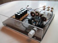
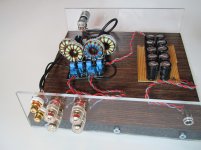
Finally managed to mod and put decent connectors for my blue/black board.
I'm not good with mechanical parts, so I build an enclosure that I could with what I had.
Mods are as follows:
Oscons for tank caps
2,2 uF Jantzen caps for input
Kemet 2.2uF ±10% 40 V ac, 63 V dc for negative side input
2305-V-RC Bourns for chokes
Murata 220nF ±10% 250V dc X7R as bootstraps
I didn't have parts for bootstrap snubber and I don't think I'm doing it any time soon. Also added 22000 uF as off board cap tank.
I like the way the amp sounds now. I still need to get some stand offs and maybe make the wire between amp and cap tank a bit shorter.
Attachments

If I ever try to build an another TPA3116 based amp, I think I would try Sure board.
Having most of the mods ready made would be convenient.
The use of diode bridge in Sure board still troubles me. Has anyone tried removing them and did the sound change at all? Also reported heating of the chip is strange. Hot running chip would prevent the change of heat sink and the original heat sink won't allow the use of bigger chokes.
Hey folks,
I apologise if this has been asked here before, as Im sure it has, but at nearing 500 pages of posts, its quite the lengthy thread!
I'd like to order a pair of these boards this weekend to play with in a few home systems and am wondering which boards to start with.
Would I be correct to assume the YJ black/blue board is the board of choice of for heavy modding, while the Sure board is the board to choose if looking for a stock solution?
I'm not afraid of minor mods, as I would like to start tinkering with, and learning more about amps. (Im good with speakers, but amps are new territory).
Cheers
Thanks for your feedback!
I have already read that it is a fullrange signal for the master amp, but what was new to me is that the treble and bass controls don't have any influence on that incoming fullrange signal. I saw some selfdrawn schematic of this board on another forum and thats why I was confused. I will try to set my scope to fft mode again to see the effects. Last time the only thing I saw was noise :/
Then I will try to locate the master and slave sync signal and check the resistors value. That's the hint I was looking for 😉 Thanks!
In case the subchannel is really low pass filtered that way, I will modify the sub input to vary the low pass freq.
I will keep you informed 😉
Thanks again.
Hi guys,
Today I had some time to try again my 2.1 amp board. As per EVM I found out that the resistor between master and slave sync shall be 4.7k and not 10k as written in the datasheet itself.
I have now replaced the 10k resistor with the 4.7k one but without success. Unfortunately it still sounds very noisy on the sub output.
Also I still don't understand completely why the treble and volume knobs have an impact on the sub channel. The description of the board on ebay says that volume and treble knobs are for the stereo channel and the bass control is for the sub channel.
I still have this 100khz signals on the sub out and also I can control the volume of the bass by twisting the bass control between zero and way too much 🙂
I checked the output caps one by one and the seem to be fine. All values as expected.
Does anybody have another idea and some further information why this behaviour is normal or is not?
Thanks in advance!
I still have this 100khz signals on the sub out and also I can control the volume of the bass by twisting the bass control between zero and way too much 🙂
This is an indication that the master/slave sync is still not working properly. When not sync'd it will self-oscillate at 100kHz. Typical carrier freq is 400kHz and if running at 100kHz, the LC filter will not be sufficient to stop the carrier freq from getting through as it is optimized for 400kHz. Fix your master/slave issue and the noise will go away.
As I said before the pots for treble and bass are most likely there to control the subwoofer XO, and not the 2.0 stereo which is full range without tone controls. Despite what the Chinese website says, that is usually how these amps are made.
Check to see if you have a 47pF cap to ground on the sync pin 16. The main datasheet spec's 1nF which is too big. It seems they got the bugs worked out on the EVM board which has correct values and the bootstrap snubber whereas the main datasheet is missing the snubber and has incorrect values on the master/slave sync. If you have a scope, probe the sync input to the sub and see what the drive level looks like and shape. It should be a 400kHz clock with at least 3 volts to work.
Very cool with the remote!
Which combination do you like/sounds better? 1, 2, or 3?
Combination 1 is better than 2,3 and YJ Blue/Black.
Finally managed to mod and put decent connectors for my blue/black board.
I'm not good with mechanical parts, so I build an enclosure that I could with what I had.
Mods are as follows:
Oscons for tank caps
2,2 uF Jantzen caps for input
Kemet 2.2uF ±10% 40 V ac, 63 V dc for negative side input
2305-V-RC Bourns for chokes
Murata 220nF ±10% 250V dc X7R as bootstraps
I didn't have parts for bootstrap snubber and I don't think I'm doing it any time soon. Also added 22000 uF as off board cap tank.
I like the way the amp sounds now. I still need to get some stand offs and maybe make the wire between amp and cap tank a bit shorter.
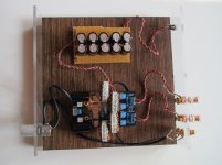
You're creating uncessary effects and letting others go because your capacitor bank isn't canceling by having the negative face a positive side.
Trust me, I've wired them like that before, for convenience, but you'll get better performance if they are not like that.
Hi destroyer,
thanks for this picture,
sorry for my stupid question:
I have for my tpa 3116 a meanwell SMPS that produce 21V DC
Can I plug the ouput to this kind of board ?
If yes, what I understand is it improves the sound as the voltage is more linear, right?
Where can I find a schema of this board, and component list ?
thanks for your answer
Can you please show how to wire the capacitor bank in your diagrams.
Would be a great help to the technically challenged.
Thank you.
That's a diagram for physical orientation of the capacitors, not the electrical wiring orientation.
The grey indicates the negative side of the capacitors.
They are not bi-polar.
camelator: SMPS's can benefit from a capacitor bank, yes. But some of them will go into current overload protection as well, when you turn them on. To fix that you either 1. have less capacitance. 2. Add an inrush current limiter. 3. Flip the switch on and off quickly a few times to get them charged because you're cheap.
Finally managed to mod and put decent connectors for my blue/black board.
I'm not good with mechanical parts, so I build an enclosure that I could with what I had.
Mods are as follows:
Oscons for tank caps
2,2 uF Jantzen caps for input
Kemet 2.2uF ±10% 40 V ac, 63 V dc for negative side input
2305-V-RC Bourns for chokes
Murata 220nF ±10% 250V dc X7R as bootstraps
I didn't have parts for bootstrap snubber and I don't think I'm doing it any time soon. Also added 22000 uF as off board cap tank.
I like the way the amp sounds now. I still need to get some stand offs and maybe make the wire between amp and cap tank a bit shorter.
Yes the cap bank orientation puzzled me here as well as what I see from the top...would need to see under the hood for it to make sense...
That's a diagram for physical orientation of the capacitors, not the electrical wiring orientation.
The grey indicates the negative side of the capacitors.
They are not bi-polar.
camelator: SMPS's can benefit from a capacitor bank, yes. But some of them will go into current overload protection as well, when you turn them on. To fix that you either 1. have less capacitance. 2. Add an inrush current limiter. 3. Flip the switch on and off quickly a few times to get them charged because you're cheap.
Pardon my ignorance - if the cap is not "bi-polar (di-polar??) why are there +ve and -ve leads? Typically only electrolytic caps are polarised and one has to watch out for the polarity during connection.
Regards,
Bootstrap Snubbers added to New Hiamp mini 65x65mm and 65x100mm Boards, all improved pop issue under the power on/off conditions.


Coming my new finished TPA amp with Motorized ALPS Pot. + IR remote control. 🙂

All Hiamp Assembled Boards [Size Comparison]


Pardon my ignorance - if the cap is not "bi-polar (di-polar??) why are there +ve and -ve leads? Typically only electrolytic caps are polarised and one has to watch out for the polarity during connection.
Regards,
I don't even know what you're asking. We're talking about electrolytic capacitor banks. This is the most rudimentary stuff there is for amplifier construction.
I don't even know what you're asking. We're talking about electrolytic capacitor banks. This is the most rudimentary stuff there is for amplifier construction.
I was confused by your post earlier when you said the caps are not bipolar. I guess I did not trace the question far back enough.
Regards,
- Home
- Amplifiers
- Class D
- TPA3116D2 Amp